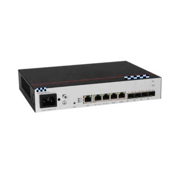
Routers and switches need to use optical modules and fiber patch cord to realize the interconnection between network devices. Usually, Gigabit switch can be matched with gigabit optical module and 10 Gigabit optical module. Optical switching represents a fundamental technological evolution, shifting data routing from the domain of electrons to the realm of photons, or light. This transition allows data to remain in its native optical form as it travels through fiber optic networks, eliminating the need for. Optical switches are devices that route light signals from one path to another without converting them into electrical signals first. They're a core component in fiber-optic networks, where data travels as pulses of light through glass fibers. Every time that light needs to change direction or jump. An SFP (Small Form-factor Pluggable) module is a hot-swappable transceiver used in switches, routers, servers, and telecom equipment to transmit data over fiber or copper connections. Different SFP modules support different: That's why selecting the correct model matters. Think of it as the “translator” for your network equipment, converting electrical signals into optical signals. Switch optical modules, which convert electrical signals to optical signals and vice – versa, and optical interfaces, which serve as the physical connection points, play a pivotal role in determining the speed, distance, and reliability of data transmission.
[PDF]
Various optically switched architecture prototypes, based on the above optical switches, have been proposed to demonstrate the potential of optical data center networks. Optical data center networks are mainl.
[PDF]
The optical module is the foundation of optical communication that provides photoelectric conversion (see Figure 2). The photoelectric conversion efficiency of optical modules is crucial, and it directly affects the quality and performance of optical communications. From the technical level, HISILICON makes improvements. These two products are part of the LIGHTPASS ® Series active optical modules expected to be used for optical interconnection applications and IOWN* structures used for data centers and other uses. Demo kits for evaluating these products will be available from September 2023, and mass production is. Microwave photonics technology (MWP), which has been applied to various radar, Telcom, Electronic Warfare systems, is now facing more and more challenging development trend of miniaturization and modular array for increasing node counts and system complexity. In the context of data communication, it involves transforming data into light pulses for transmission through optical fibers and converting received light signals back into electrical. The optical module is the key device in all the links of this circulation process (see Figure 1). Two modules are used in pairs. The radio-frequency signal.
[PDF]
In this paper, a thermally tuned silicon-based three-channel reconfigurable multimode interference (MMI) optical power splitter with four optimized thermal isolations is proposed. Specific and flexible reconfig-urable functions (1, , and MMI splitters) can be achieved by. Abstract: We demonstrate integrated photonic circuits for quantum devices using sputtered polycrystalline aluminum nitride (AlN) on insulator. 56(1), 017106 (2017), doi: 10. The two most common types of splitters offered are polarizing beam splitters and polarization maintaining beam splitters. Their operating principles are as follows: Polarization Maintaining. optical transimission & integration needs of any system. MEISU specializes in precise custom fiber array sub-assemblies and PM fiber optical components and assemblies for different areas like integrated optics, sensoring, healthcare, spectroscopy, etc., 50/50 FBS, can be used as the frequency-mode Hadamard gate for frequency-encoded photonic qubits. Quantum cryptography is the key point of quantum communication. In classical cryptography classical bits are used but in quantum cryptography quantum bits (qubit) are used. Quantum communication sends the information through some channels such that, optical fibre, satellite etc.
[PDF]
An optical power meter is an electronic device that measures the power of an optical signal. It helps engineers verify the performance of optical fiber systems, ensuring that the signal strength meets requirements, and is an essential tool for communication network maintenance and. An optical power meter (OPM) is a device used to measure the power in an optical signal. Other general purpose light power measuring devices are usually called radiometers, photometers, laser power meters (can be. An optical power meter (OPM) measures the power levels of light signals in devices that transmit data or power using light. The term "optical power meter" may sound generic, but in popular usage, it specifically implies a fiber optic power meter. For light power measurements outside the field of. Optical Power Meters (OPMs) are crucial instruments in the field of optical sensors and fiber optic communications. It provides an expert-curated supplier directory, buyer-focused technical background information, and structured selection criteria to support professional procurement decisions. It measures optical power directly, and it is also used in loss testing when paired with a stable light source.
[PDF]
Frequent status changes from up to down or vice versa in the ports logged by the switch port syslog indicates a port flap. On a big industrial plant we've replaced an old HP switch with a brand new couple of C2960x switches in stack configuration and ever since then, every 6/8 hours or so, the two fiber optics links of switch #2 go down at once. These are connected to a ring of 3 similar other access switches, that. EX4650 2-switch virtual chassis, running version 19. 2, optic p/n 740-031981 (SFP+-10G-LR) is plugged into port xe-0/0/10 and connected to an ISP via single mode fiber. Nothing special is configured on the port, it is running at 10G speed, show interfaces diagnostics optics shows that it's. This article describes steps to diagnose the Continuous port flapping on a FortiSwitch. Verify Cable Connection: Ensure the cable is properly connected between the switch port and the end device. Run the command below on FortiSwitch multiple times and check the. Real head scratcher this morning that I'm hoping someone can help me with! The port on our core switch (HP A5500) that our Smoothwall box is connected to keeps going up and down. Port flapping, also known as link flapping, causes a switch port's state to fluctuate between up and down within concise periods of time. This instability caused by flapping ports affects network connectivity. Port flapping is a common network issue that can disrupt communication between devices and degrade overall network performance.
[PDF]
The CFP standard defines a pluggable optical transceiver form factor capable of supporting 40G and 100G Ethernet, OTN (Optical Transport Network), and SONET/SDH protocols. The acronym "CFP" represents the Roman numeral "C" (100), aligning it with 100 Gigabit Ethernet. Originally introduced as the first standardized pluggable solution for 100 Gigabit Ethernet, CFP (C Form-factor Pluggable) modules were engineered to support high-bandwidth, long-distance transmission using multiple optical lanes. Their robust design made them ideal for carrier-grade networks, DWDM. The C form-factor pluggable (CFP, 100G form factor pluggable, where C is Latin: centum "hundred") is a multi-source agreement to produce a common form-factor for the transmission of high-speed digital signals. Developed collaboratively. The CFP optical transceiver module is a standardized, hot-swappable optical transceiver used for high-speed data transmission in telecommunications and data center networks. CFP transceivers are defined by CFP MSA to enable 40 Gb/s, 100 Gb/s and 400 Gb/s applications. It features a new concept known as. This article breaks down the key differences between CFP, CFP2, CFP4, and CFP8 optical transceivers commonly used in fiber optic networks. Figure 1: Dimensions of CFP, CFP2, CFP4, and CFP8 The table below summarizes the specifications of each form factor: 24 W (Max. ) In essence, the progression.
[PDF]
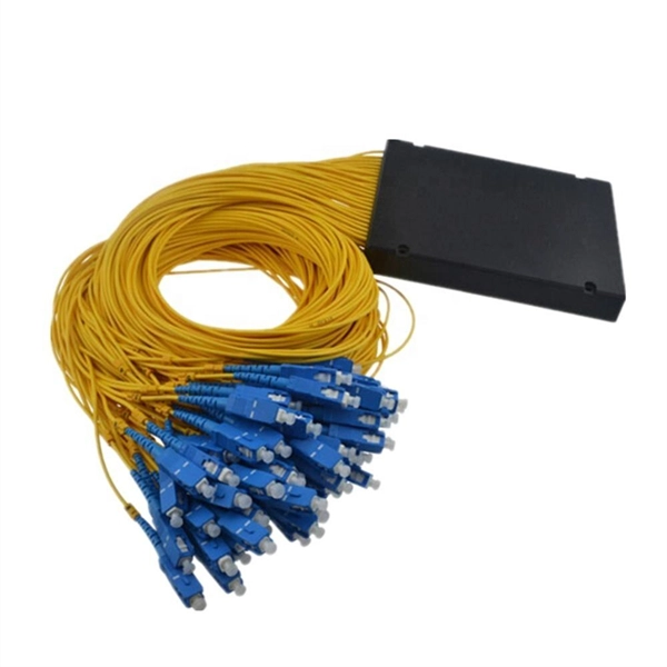
This paper aims to study the design, simulation, and optimization of low-loss Y-branch passive optical splitters up to 64 output ports for telecommunication applications. For a waveguide channel profile, the standard material silica-on-silicon is used. Two important technologies for optical layer monitoring are Optical Performance Monitoring (OPM) and Optical Power Detection (OPD). Although they aim to maintain network health, they differ significantly in scope, technique, and deployment. This article delves into these differences, equipping. Optical Performance Monitoring (OPM) is considered a necessity over an optical network to enable sensibility of traffic line status and attain outstanding Quality-of-Service (QoS). The Y-splitters are designed and simulated at. Passive optical networks (PONs) are the network architecture of choice for residential fiber deployments. A PON is designed specifically to be cost-effective for delivering high data-rates to large customer populations. signals and various components of OPM functionalities are indispensable robust network operation and plays a key role flexibility and improve overall. Optical performance monitoring (OPM) is used for managing high capacity dense wavelength-division multiplexing (DWDM) optical transmission and switching systems in Next Generation Networks (NGN). OPM involves assessing the quality of data channel by measuring its optical characteristics without.
[PDF]
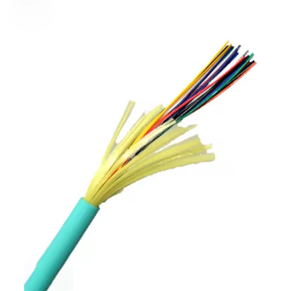
Total number of cores = Number of branches × Number of cores per branch If there are no branches, the number of branches equals one. For example, an MTP®-8 trunk cable with four branches and eight cores per branch has a total of 32 cores (4 × 8 = 32). For example, if you have three optical fiber access switches, you need to have three cores. (actually use a four core optical cable) This is because apart from one-core optical fiber, there are basically no optical cables with an odd number of cores, such as three-core, five-core, etc. It is worth. Fiber cores are the heart of fiber optic cables, transmitting light signals that carry data. Made from either high-quality glass or plastic, the core plays a critical role in determining the cable's performance. The total number of cores for a 1pc fiber patch cable is calculated as the number of. One key factor is the number of cores, which impacts how much data you can transmit. Single-mode: A. Common fiber cores include 1 core, 2 cores, 6 cores, 8 cores, etc., and there are many types. This article will focus on the number of fiber cores, introducing their respective characteristics and usage scenarios. Of course, this is a general situation, and it can be considered as follows: 1.
[PDF]
XGS-PON is a 10 Gbps symmetric passive optical network (X=10, S=symmetric). Optical fiber's greater transmission capacity and speed deliver upstream and downstream (symmetric) speeds of up to 10 Gbit/s (gigabits per second) on the road to connecting users in the last. 10G-PON (also known as XG-PON or G. 987) is a 2010 computer networking standard for data links, capable of delivering shared Internet access rates up to 10 Gbit/s (gigabits per second) over optical fibre. This is the ITU-T 's next-generation standard following on from GPON or gigabit-capable PON. It is commonly used to implement the link to the customer (the last kilometre, or last mile) of fibre-to-the-premises (FTTP) services, using a. Short on Ethernet ports and looking to connect an extra device or two to your wired network setup? You're likely to encounter two options: an Ethernet splitter, and an Ethernet switch. Here's why you should choose the switch every time. What Is an Ethernet Splitter? An Ethernet splitter is a simple. Recommendation ITU-T G. 1 describes a flexible optical fibre access network capable of supporting the bandwidth requirements of business and residential services and covers systems with nominal line rates of 2. 4 Gbit/s in the downstream direction and 1. 984 G-PON and ITU-T G. 9807 XGS-PON wavelengths to coexist within the same single mode fiber cabling and across the same passive optical distribution splitters. This means that users can.
[PDF]
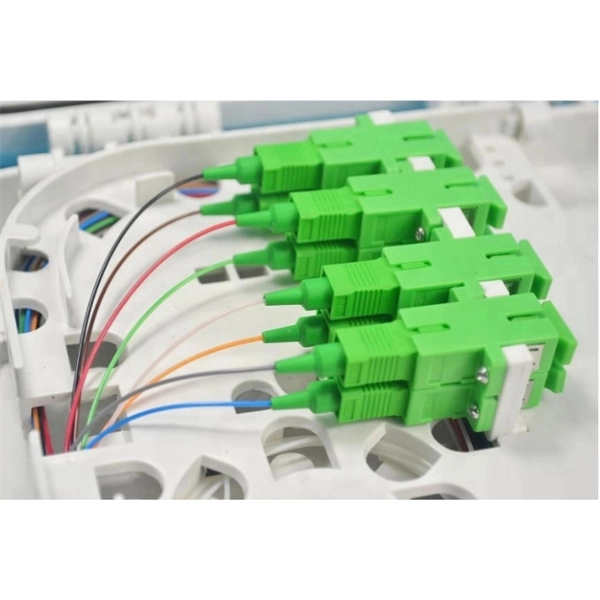
This step-by-step guide aims to provide a comprehensive understanding of the techniques and considerations involved in successfully connecting optical fibers, offering invaluable insights for professionals and enthusiasts in the field. In high-speed data networks, the seamless integration of fiber optic cables with SFP (Small Form-Factor Pluggable) modules is critical for reliable signal transmission. SFP transceivers bridge electrical and optical signals, making them indispensable in data centers, telecom networks, and. Proper connection of fiber optic cables is essential to harness these benefits fully, as even minor errors can lead to significant performance issues like signal loss. This article will guide you through the necessary tools, materials, and methods on how to connect fiber optic cables effectively. This section describes how to install optical transceivers on the SFP or SFP+ ports and connect them to the ports of the peer device using optical fibers according to the network plan. The USG supports both 1 Gbit/s, 10 Gbit/s, and 40 Gbit/s optical modules. The optical modules at both ends are. There are many types of fiber optic connectors, including SC, LC, FC, ST, D4, MU, MT/MPO, etc. These connectors can be divided into single-mode and multi-mode fiber optic connectors according to their structure and purpose. In this tutorial.
[PDF]
Multi-mode optical modules can only be used for short-distance transmission (SR) due to serious inter-mode dispersion; while single-mode optical modules are mostly used for long-distance transmission such as LR, ER, and ZR. Whether you are in need of single-mode optical modules for lines that require high transmission rates and long distances, or multi-mode optical modules for short-distance transmission scenarios with numerous network nodes and connectors, you can find the optical modules you desire at the LINK-PP. Single-mode fiber uses a 9/125 µm core/cladding structure that supports only one propagation mode, which minimizes modal dispersion and allows signals to travel tens of kilometers with low attenuation. Multimode fibers have larger cores (typically 50/125 µm or 62. Under normal circumstances, the transmission distance of less than 2km is. An optical fiber is a cylindrical dielectric waveguide composed of a central core surrounded by cladding with a slightly lower refractive index. This carefully engineered index contrast confines light within the core through total internal reflection, enabling optical signals to travel with. If your network requires long-distance transmission (over 550 meters), a single-mode optical module is the best choice. For shorter distances, multi-mode modules are more appropriate. Single-mode modules offer higher bandwidth capabilities, making them suitable for high-speed data transmission.
[PDF]
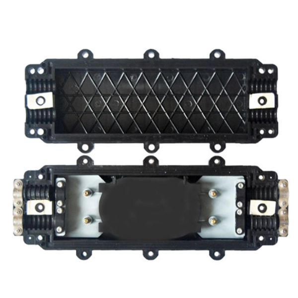
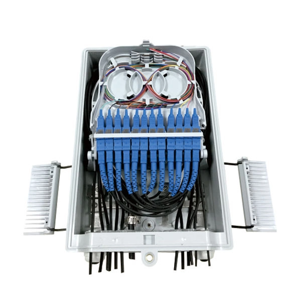
OPGW cable joint box installation involves several key stages: selecting the appropriate location, preparing both the cable and the joint box, splicing fibers, and sealing the joint box properly. Adhering to these steps ensures optimal performance and longevity of the telecommunications system. Optical fiber junction boxes are essential components in outdoor optical fiber cable installations. In this article, we will discuss the necessary steps and best practices. The Indoor/Outdoor Splice Box is a wall-mounted, indoor/outdoor fiber splice enclosure for centralized splice-only applications. These boxes are well suited as optical cable splice collection points for MDU (Multi-Dwelling Unit) residential fiber network applications, MTU (Multi-Tenant Unit). The installation of an optical cable junction box is crucial in ensuring the integrity and performance of optical networks. As we enter 2024, adhering to best practices not only enhances system reliability but also mitigates potential issues that can affect customer experiences. Installing a fiber optic splice closure efficiently and effectively requires attention to detail and. AFL's SB01 splice enclosure provides protection from all types of elements. From weather to bullets, the iron and steel construction requires no additional protective covering. Furnished with four plugged cable ports (2 aluminum and 2 plastic) for either All-Dielectric Self-Supporting (ADSS) or.
[PDF]
Lasers, modulators, and photodiodes form the core architecture of optical transceivers, enabling light-speed communication across global networks. Lasers generate the optical carrier. Modulators encode digital information. An optical transmitter is a crucial device used in fiber optic communication systems. Its primary function is to convert electrical signals into optical signals It involves modulating electronic system data and transforming it into light pulses using a laser or LED, and sending the pulses through. The optical transmitter and the optical receiver are the core components that enable this process, forming the electronic-to-optical and optical-to-electronic gateways necessary for modern, high-capacity data transmission. It takes data from an electronic system, uses a laser or LED to modulate that data into pulses of light, and then sends those pulses down the fiber. Together, lasers, modulators, and. At the core of a fiber optic system is the optical fiber – a flexible, transparent strand of glass, thinner than a human hair. Optical fiber is formed by drawing glass or plastic to a diameter slightly thicker than that of a. What are the main elements of an optical transmitter? Data decoder/demodulator, electrical interface, detector, optical interface.
[PDF]
Active Optical Cables simplify high-speed networking by embedding tiny optical transceivers directly into the cable ends. Inside one compact assembly, electrical signals convert to light pulses, travel through the fiber core, then reconvert to electrical form—eliminating separate. When traditional copper cables hit their physical limits, Active Optical Cables (AOCs) emerge as the superior solution for demanding, high-bandwidth applications. These change electrical signals into optical signals and back. This gives. Active optical cable (AOC) is a high-performance communication cable used for short-range multi-lane communication and interconnected applications. Unlike traditional fiber-optic cables, which require external transceivers to send and receive signals, AOC cable have the necessary transceivers integrated. Thanks to the intricate design of Active Optical Cables, which allows for flexibility and gives an extra advantage of unmatched stability. Alt Text: A Group of AOC Cables with Different Connectors In the following paragraphs, you will be broadly enlightened about every aspect of the cutting-edge. Active Optical Cables (AOCs) are an innovative type of data transmission technology that has come forth to fill the gap between the old copper cables and the ever-advancing fiber optics. Unlike the traditional methods, AOCs are explicitly structured to provide long-distance connecting devices to.
[PDF]