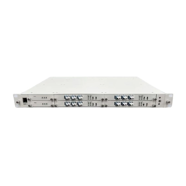
The panel can be pre-loaded completely with the required adapters or pre-loaded with pigtails and splice accessories. The tray is locked by 2 plastic latches and lowers to a 45 degree angle when fully extended. Installation and labeling are simple and easy. FS offers FHD® FAPs and FHU® 1U fibre patch panel with LC, SC, MTP®/MPO connectors in singlemode/multimode fibre to deploy medium for high-density fibre optic network applications. A patch panel or fibre distribution panel is a metal frame with pre- punched holes equally spaced horizontally along the front face. Unpopulated patch panels can be configured with bulkhead. A carefully selected range of fibre optic termination and patch panels from leading brands including Panduit, Canford and Speedway. A handy tool to for quickly finding a populated fibre connection panel that meets your requirements. Rack mounted fibre patch panels create a convenient, professional and easy access way to organise your fibre cables into a cabinet. Latest Optical Fibre Patch Panels for fibre installations.
[PDF]
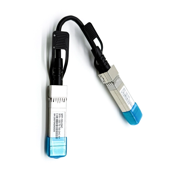
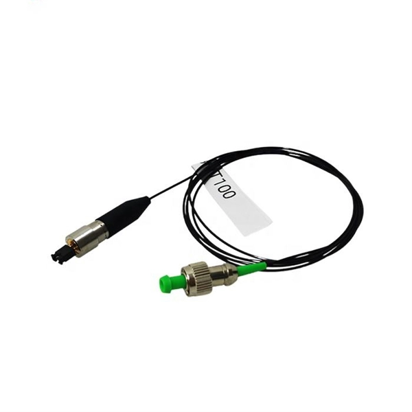
Insert a compatible SFP transceiver into the converter's port, making sure it matches the network's media type and speed. Then, connect one end of the fiber cable to the transceiver and the other to the appropriate port on a switch, router, or another media converter. Fiber media converters translate copper's electrical signals into fiber's optical signals, and back again. This allows networks to extend beyond the 100 m copper limit while gaining higher bandwidth and resistance to electromagnetic interference. In the illustrated setup, each LAN links to a. A fiber media converter is a networking device that allows you to convert a signal from one medium to another. This allows you to connect devices that use different types of cabling, such as a computer. While fiber optic ports are becoming increasingly common on networked electronics, the majority of connected devices still rely on RJ45 twisted pair connections. To help bridge the copper-fiber divide, media converters and transceiver modules (also known as SFPs or mini-GBICs) are often required. Use Fiber Media Converter in Your Network Media converters today are widely deployed in all. It is a device used to convert fiber optic cables to Ethernet cables to provide better connectivity. It is necessary to convert fiber optic signals to Ethernet signals because many network devices can only communicate with Ethernet signals. Fiber optic cables are known for the unmatched speed.
[PDF]
This diagram highlights media converters, switches, and cable types. Also thanks to Init7 (for the great service), r/FiberOptics and FS for providing me with what I needed to get this setup going. If you find this article useful and you are considering Init7 as your provider you can use my referral code “20700408098” to get CHF 111. - off hardware and also support me. Keeping this page as a placeholder for now. Have any questions? Talk with us directly using LiveChat. A fiber optics network diagram illustrates how high-speed data travels from an internet service provider to end users. By using light signals, fiber optics provide faster speeds and better reliability than. MS Visio has long been the default choice for drafting fiber network diagrams, and with the right stencil libraries it can be used to draw everything from backbone routes to detailed patch panel layouts. When fiber techs look for visio fiber stencils, they are usually solving a very practical. Be among the first to receive important product updates, insights and news. Fiber optic cable is used for everything from demarcation point wiring to network signal distribution to video signal extension. Often, fiber enters the structure to a centralized rack or data room where it is connected to a modem. The modem connects to a network switch which connects each remote.
[PDF]
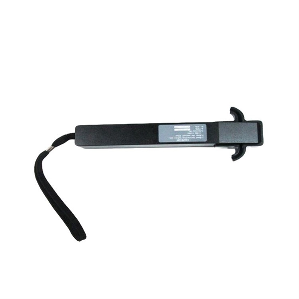
The extinction ratio tester is a precision instrument specially used to measure the quality of modulated signals in optical fiber communication systems. It is mainly used to evaluate the extinction ratio performance of the optical signal output by the laser or modulator. Product Type Outlook (Optical Extinction Ratio Testers, Digital Extinction Ratio Testers, Others), Application Outlook (Telecommunications, Data Centers, Healthcare, Others), End-Use Outlook (Industrial, Commercial, Residential) The Extinction Ratio Tester Market size was estimated at USD 0. 15. Extinction ratio tester-Product Resources,Ideal PhotonicsSpecializing in global instrument distribution and system integration for MCT detectors, semiconductor laser diodes, mid-infrared QCL lasers, fiber amplifiers, photodetectors, HeCd lasers, gas lasers, narrow-linewidth lasers, OCT system fiber. The global Extinction Ratio Tester market size is expected to reach $ 236 million by 2031, rising at a market growth of 5. 7% CAGR during the forecast period (2025-2031). The telecommunications sector dominates consumption, driven by the deployment of 100G/200G/400G optical modules in 5G fronthaul and data center interconnect. The global Extinction Ratio Tester market size is predicted to grow from US$ 161 million in 2025 to US$ 229 million in 2031; it is expected to grow at a CAGR of 6.
[PDF]
The BERT800 series bit error tester employs a modular design, featuring a control board and interchangeable interface boards. This flexible architecture allows for testing a wide range of optical transceiver modules with different packages, including OSFP, QSFP-DD, and QSFP28. Bit Error Rate (BER) is an important factor in the performance of any data transfer channel, whether wired or wireless. It can be affected by a variety of factors, including signal to noise, distortion, and jitter, so accurate BER measurement helps to pinpoint problems. We offer a full range of. The global bit error rate tester (BERT) market is expanding significantly, driven by escalating demands for high-speed data transmission validation. Current estimates place the market at approximately $XX billion in 2024, with a projected CAGR of 8. The bit error rate (BER) represents the ratio of incorrectly received bits to the total number of transmitted bits over a. A bit error rate test (BERT) typically requires a test pattern generator and a receiver set to the same pattern. They can be used in pairs, with one at either end of a link, or singularly at one end with a loopback at the remote end. Versatile 10G multiservice test modules for lab and field. As transmission rates continue to accelerate, accurately measuring bit error rates in optical modules is crucial to ensure reliable performance.
[PDF]

A relay protection tester is a core device used to verify the performance of relay protection devices. Its working principle can be summarized as “signal excitation – behavior detection. ”. Circuit principle of relay protection tester 1, input AC220V power output control relay K1 is approved by the insurance into the dual voltage regulator for T1 input carbon brush, through large knob to adjust the power into the isolation transformer T1 T2 (part-time riser), heat flow device points. When the transformer wiring type is Y/Y (Y0), the test wiring is very simple: when testing phase A, the tester IA is connected to the phase A of the high voltage side, and the tester IB is connected to the phase a of the low voltage side. ” The tester has a built-in high-precision programmable power supply, capable of simulating various operating. This handbook covers the code of practice in protection circuitry including standard lead and device numbers, mode of connections at terminal strips, colour codes in multicore cables, dos and donts in execution. The following is a detailed summary. This Playlist is assigned to sessions of protection Relays Principles. First, a description of Simple Functions.
[PDF]
Specifically designed for settings-based protection testing with a high degree of automation, our modular software Test Universe offers numerous functions and application-optimized test modules that save yo.
[PDF]
With the bandwidth and performance demands on Ethernet networks increasing daily, BERT has become essential for quantifying bit error rate in optical fiber communication channels and establishing confid.
[PDF]
Figure 1 shows the OCS architecture containing the soliton microcomb, SOAs, AWGs in the switch and AWGRs to route the data across many racks (cf. Methods). This architecture allows further paralle.
[PDF]
In this article, you will learn the step-by-step process of testing your solar panels using a multimeter. We will cover the essential tools you need, the specific measurements to take, and how to interpret the results. By the end of this guide, you will be equipped with the knowledge to diagnose. Solar panels are usually tested under standard conditions using a light source that mimics the light from the sun on a clear day. You can use the following method if you want to test your solar panel under standard conditions. Testing solar panels is easy with a multimeter! To test the current. Your multimeter is your best friend when testing solar panels. You can use it to check: Here's how: Multimeter — I recommend getting one that is auto-ranging. Also, a simple voltmeter won't work here. You need a multimeter that can measure both volts and amps. Locate the open circuit voltage. Learning to test a solar panel with a multimeter is an investment in your knowledge and ability to manage your own solar energy system or provide valuable services in the growing solar industry. Measure Voc (open circuit voltage) — if it reads 0V, the panel or wiring is dead. If it reads 60–80 % of rated, a bypass diode has failed. Perfect for DIY solar builders, RV owners, o. more Audio tracks for some languages.
[PDF]