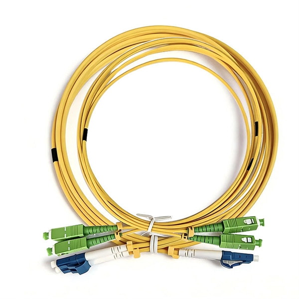
The 12-Core configuration of the MTP cable refers to the number of fibers within a single connector. This design allows for efficient data transmission and is particularly well-suited for high-density applications where space optimization is critical. According to the IBDN standard, we generally recommend using 12 cores for the communication room in each building, and 24 cores for the building room. Of course, this is a general situation, and specific words may consider according to the following criteria. Number of wiring points and switches. Optical fiber cables are used to transmit large amounts of data over long distances. In this article, we will discuss the differences between these two cables in terms of their. However, if there were no cores, fiber optic cables would be useless. The reason is that cores are basically hidden components located that receive the light signals. Don't worry, in this guide, we'll discuss in detail what the fiber optic core is and its role in data transmission. Moreover, we'll. Among the various types of fiber optic cables available, the 12 core fiber optic cable is a common choice for many applications due to its balance of capacity and flexibility. Made from either high-quality glass or plastic, the core plays a critical role in determining the cable's performance. Multimode fiber optic cables can carry multiple light modes or signals, making them ideal for.
[PDF]
According to the IBDN standard, we generally recommend using 12 cores for the communication room in each building, and 24 cores for the building room. Of course, this is a general situation, and specific w.
[PDF]
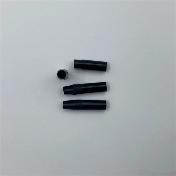
EIA/TIA 568 B allows any fiber optic connector as long as it has a FOCIS (Fiber Optic Connector Intermateability Standard) document behind it. Fiber optic cold connection, also known as mechanical splicing, is a widely used method of connecting optical fibers in a network. Unlike fusion splicing, which uses heat to join two optical fibers together, cold connection uses mechanical means to create a stable and low-loss connection. Unlike fiber splicing, which is permanent, connectors allow for easy connection and disconnection of cables, making them ideal for maintenance and flexibility in. Fiber optic joints or terminations are made two ways: 1) splices which create a permanent joint between the two fibers or 2) connectors that mate two fibers to create a temporary joint and/or connect the fiber to a piece of network gear. These terminations must be of the right style, installed in a. Fiber termination refers to the process of preparing the end of a fiber optic cable to connect to another fiber, a device, or a network. Proper termination is essential for ensuring optimal performance, reducing signal loss, and maintaining the durability of the connection. Since the introduction of fiber optic technology decades ago, a variety of connector types have been.
[PDF]
There are currently three methods of looking inside a fiber optic connector: (1) Non-destructive X-ray (2) Lossless sonar (3) Destructive cross section These methods help engineers determine the causes and effects of fiber optic connector failures and monitor the connector assembly. There are currently three methods of looking inside a fiber optic connector: (1) Non-destructive X-ray (2) Lossless sonar (3) Destructive cross section These methods help engineers determine the causes and effects of fiber optic connector failures and monitor the connector assembly. Fiber Optic Center offers a unique cross-sectioning service to identify and isolate problems related to fiber optic terminations that would otherwise be invisible. All. There are two major uses for visual inspection of fiber optic connectors. Video microscopes should have ability to record images and some may have ability to analyze connector condition to standards. Look for dirt, contamination, scratches or any other problem. Since connectors are susceptible to damage that is not immediately obvious to the naked eye—the inspection phase is vital. When proceeding with the inspection of connectors, there are two main components to inspect: the connector itself and the ferrule. With the press of a single button, FOCIS Flex auto-focuses, captures and centers the end-face image, applies Pass/Fail rules, displays image and Pass/Fail results, saves results internally and/or wirelessly transfers data to a.
[PDF]

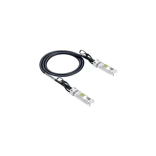
In this guide, we'll walk you through the entire process of preparing fiber optic cable for splicing and termination to fiber connectors. We'll explore the necessary tools, safety precautions, and step-by-step procedures for cable connectors, mechanical and. This article will guide you through the necessary tools, materials, and methods on how to connect fiber optic cables effectively, ensuring you achieve optimal performance from your fiber optic network. Have a network installation project? Fiber Optic Cables: The primary medium for your connections. There are many types of fiber optic connectors, including SC, LC, FC, ST, D4, MU, MT/MPO, etc. These connectors can be divided into single-mode and multi-mode fiber optic connectors according to their structure and purpose. Fiber optic connectors play an essential role in the realm of optical communication, enabling seamless connections between fiber optic cables. At the heart of any robust fiber optic network lies a crucial process: Preparing a fiber cable for termination of a connector or splice. Whether you're installing a new network, expanding an existing one, or. Fiber optic internet delivers blazing-fast speeds and reliable connectivity, making it a top choice for modern homes and businesses.
[PDF]
The wire nut size charts below will direct you to manufacturer specific guidelines (By wire nut color and sizing). Twist-On Wire Connectors These are normally twisted on by hand and have external grooves or wings for easy handling. Twist-on connectors are usually color-coded to indicate their size or capacity. They are easy to twist on and off when needed and are commonly used in electrical wiring systems for light switches, ceiling fans, receptacles or outlets. Connectors are represented in the schematic circuit diagrams of electronic circuit designs in a number of ways. Normally the symbols are quite obvious, but they are dependent on the actual system used, and the notations used for the connector circuit symbols may vary slightly. In addition to the basic contact symbols used for the connections themse.
[PDF]
Positive busbars, which collect all positive connections. Key Steps: When wiring a pair of 12V busbars, connect the positive terminal of each load to a stud on the positive busbar and their negative terminal to a stud on the negative busbar. 5' above batteries on inside of cockpit combing below decks. Install one new positive bus bar beside the negative one separated by about two inches 3. Positive and negative busbars are physically identical apart from the red/black colours used by some manufacturers to visually differentiate between. A Complete Guide to Battery Terminal Connector Types The store will not work correctly in the case when cookies are disabled. JavaScript seems to be disabled in your browser. For the best experience on our site, be sure to turn on Javascript in your browser. Skip to Content Blog Sign In Create an. This image illustrates a standard car battery with top post terminals and labeled connectors for the positive (+) and negative (–) ends, emphasizing safe and correct installation. A battery terminal connector is a fitting or clamp that attaches to a battery's terminal to connect a cable. In other. Both positive and negative terminals are the soul of the electrical system of the car, allowing the engine to start while keeping other components running. The catch? Mix-up or loose connection can cause electrical failure, drained batteries, and damage to wiring. This blog guides you how the two.
[PDF]