Your eyes contain two types of light-sensing cells: rods and cones. Rods detect low-light vision and motion, while cones handle color vision and detail in bright light. Damage to either can lead to vision problems like night blindness or color blindness. Protecting your eyes with proper nutrition. Personnel Safety. Optical Touch Buttons. Self-contained Sensors. Each technology has unique strengths and weaknesses, so the requirements of the application itself will determine what technology should be used. This article is focused on photoelectric sensors and defines what they are, their adv ors are readily present. Quality Control: They can detect defects, ensure proper product placement, and verify the presence of components. Safety: They can be used to create safety barriers, preventing machinery from operating when a person or object is in a hazardous zone. In this section, we explore the geometric optics of the eye. Early thinkers had a wide array of theories regarding vision. Euclid and Ptolemy believed that the eyes emitted rays of light;. Understanding the eye involves examining how its individual parts contribute to the overall function. Vision begins as light enters the eye through the cornea, a transparent, dome-shaped outer.
[PDF]
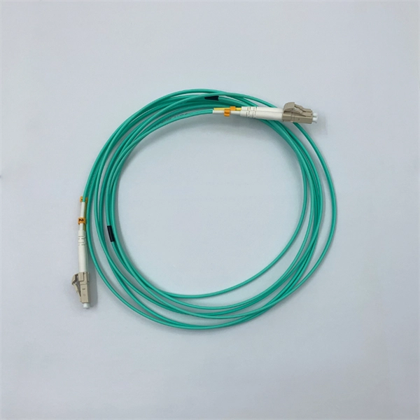
In telecommunications, an eye pattern, also known as an eye diagram, is an oscilloscope display in which a digital signal from a receiver is repetitively sampled and applied to the vertical input (y-axis), while the data rate is used to trigger the horizontal sweep (x-axis). It is so called because, for several types of coding, the pattern looks like a series of eyes between a pair of rails. It is a too. CalculationThe first step of computing an eye pattern is normally to obtain the waveform being analyzed in a quantized form. This may be done by measuring an actual electrical system with an oscilloscope of sufficient bandwidth,. Each form of baseband modulation produces an eye pattern with a unique appearance. The eye pattern of a signal should consist of two clearly distinct levels with smooth tra. Many properties of a can be seen in the eye pattern. applied to a signal produces an additional level for each value of the signal, which is higher (for pre-emphasis) or lower (for de-emp.
[PDF]
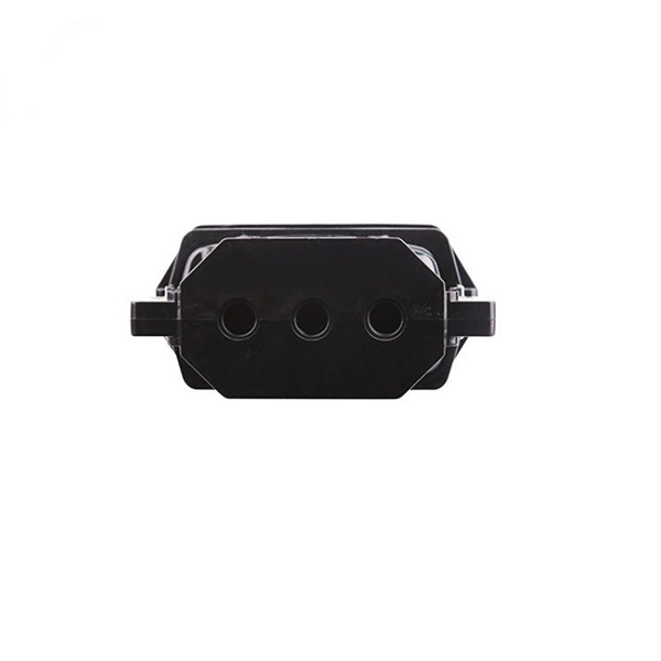
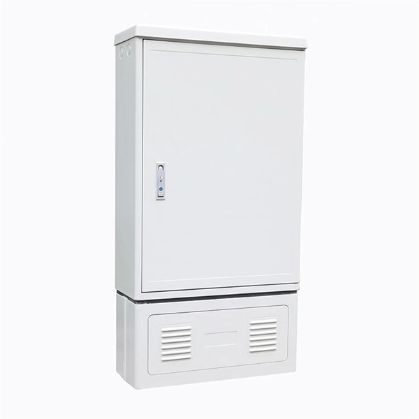
The primary function of a feeder wire is to facilitate bulk power transfer from a central source to a subpanel or a secondary distribution center. An example is the large cable running from the main service panel to a subpanel in a detached garage, basement, or workshop. A main panel and a sub-panel are both important components of an electrical distribution system. It is usually located where the main electrical service enters the building, often on an. Main feeder wires are the arteries of a building's electrical system, designed to safely and efficiently transport a large volume of power from the service entrance to secondary distribution points. They form the backbone of the electrical distribution network, handling the substantial current. An electrical sub panel, also known as a sub distribution board or sub circuit breaker panel, is a smaller secondary panel connected to the main electrical panel in a building. It serves as an extension of the main electrical panel to distribute power to different areas or circuits within a. Distribution board is a safe system designed for house or building that included protective devices, isolator switches, circuit breaker and fuses to safely connect the cables and wires to the sub circuits and final sub circuits including their associated Live (Phase) Neutral and Earth conductors. The distribution box acts as the center of power distribution, distributing electricity to all connected devices.
[PDF]
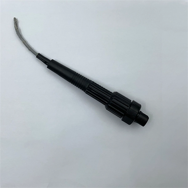
A T-tap wire connector, also known as a T-splice connector, is used to tap into existing wires and is characterized by its T-shaped design with three points of entry for wires. This allows you to install the connector on a wire and tap into it from the third entry point. The wall-mounted bracket features an integrated coupler for quick and easy installation, enhancing overall work efficiency. Corrosion-resistant galvanized coating protects against bad weather, moisture, and rust - ensures a long service life even in harsh environments. T-shape design provides both. How can we improve? Choose from our selection of T-connectors, including stainless steel pipe and pipe fittings, brass and bronze pipe and pipe fittings, and more. Same and Next Day Delivery. The NavePoint 00406777 electro zinc plated wire mesh cable tray t-shaped wall bracket is an ideal solution for neatly routing and organizing cables. Fast Docking Coupler Bar for Wire Mesh. Toolless Adapter Fitting for Fiber. The L-com LC-CRP100 T-shaped wall bracket offers a perfect way for mounting and securing the wire mesh cable tray to the wall. Made by Quest Manufacturing, this add on accessory is durable and reliable, and will hold the wire mesh safely, so you can place cables & wires in. Design Shape This bracket is designed with a T shape which provides support.
[PDF]