SFP28 (Small Form-Factor Pluggable 28) is an enhanced version of SFP+, designed to support 25Gb/s data rate transmission while maintaining the same package type. SFP28 is backward compatible with SFP+. However, compatibility can vary based on the specific SFP models, networking equipment, and vendors involved. It's advisable to consult your vendor for precise information regarding compatibility. ①. This article helps network engineers and field techs confirm SFP backward compatibility when mixing SFP, SFP+, and SFP28 optics in the same switching ecosystem. You will get concrete specs, a decision checklist, and troubleshooting patterns that show up in daily operations. ① Plug a 1000BASE-SX SFP transceiver into the SFP port on a gigabit. Common form factors are SFP (1 G), SFP+ (10 G), SFP28 (25 G), QSFP+ (40 G) and QSFP28 (100 G). The question we answer below is simple: “Which of these can I mix and match without killing the link? What “compatibility” really means? All reputable transceivers follow the Multi-Source Agreement (MSA). SFP28 optical transceiver modules provide a transmission rate of 25 Gbps and use LC connectors. 25G SR/eSR are not supported for use. Q: Can I use an SFP transceiver in SFP28 ports? A: Yes, you can. However, it's important to note that while SFP transceivers and cables can be plugged into SFP28 ports, they won't support the higher 25Gb/s data rate of the SFP28.
[PDF]
As illustrated in typical SFP internal structure diagrams, the module's core components include an optical transmitter assembly (TOSA), laser driver, optical receiver assembly (ROSA)—some high-sensitivity modules (like L16. 2) use APD receivers, which require an additional booster. As a key element in optical communication systems, optical transceivers serve as media between network devices to transmit and receive data. There has been lots of articles and guides on transceiver modules in the perspective of the package type while only a few of them cover the internal elements. Optical modules are devices used to connect network devices, transmit and receive data between network devices, and can be used to convert optical and electrical signals. The optical module is a very important component in an optical communication system. When you remove the metal housing of the optical transceiver, you will find that the internal components are connected to each other. The following section will focus on. In the era of 5G, AI, and high-speed data centers, optical modules serve as the core bridge for converting electrical signals to optical signals (and vice versa), enabling fast, reliable data transmission across networks. Among various optical module form factors, SFP (Small Form-Factor Pluggable). The optical transceiver module is mainly composed of three parts: housing, optical device and integrated circuit board. The following section will focus on.
[PDF]
Gigabit is a decimal unit defined as per SI standard. 1 Gigabit = 1000 Megabits. The unit symbol for Gigabit is Gbit or Gb. Abbreviated as Gb, a gigabit is a method of measuring data transmission. When the "b" is uppercase, like GB, this refers to a gigabyte. What comes before a gigabit? What comes after a gigabit? Gigabit vs. other data measurements. What comes before a. Gigabit single-mode fiber optic module Common parameters of optical modules 1. Center wavelength 1) 850nm (MM, multi-mode, low cost, but short transmission distance, usually only 500M); 2) 1310nm (SM, single mode, large loss during transmission, small dispersion, generally used for transmission. In computer networking, Gigabit Ethernet (GbE or 1 GigE) is the transmission of Ethernet frames at a rate of a gigabit per second. The most popular variant, 1000BASE-T, is defined by the IEEE 802. It came into use in 1999 and has replaced Fast Ethernet in wired local networks due to. What is 1 Gig in Mbps? 1 Gigabit (Gb) is equal to 1000 Megabits (Mb). This conversion is important to understand because data transfer rates are commonly measured in Mbps, but many internet plans, network devices, and even transceivers are rated in Gbps. So. A gigabit (Gb) is a unit of digital information equal to 109 bits, or 1,000,000,000 bits. It uses the standard SI decimal prefix 'giga-'. It is important to distinguish.
[PDF]
The transceiver is available as a mini-GBIC form factor, making it ideal for environments that require many fiber connections by taking up less space in your cabinet and/or computer room. Compatibility in your network is everything, and the Intellinet SFP Transceiver Module delivers. Use it with any Intellinet SFP equipped network switch or any other MSA-compliant, SFP-enabled switch. And since the Intellinet SFP transceiver module is set to broadcast the vendor on GLC-LH-SM, compatibility to your Cisco gear is provided. No need to power down your LAN switch in order to install or remove the transceiver. This makes it very convenient and easy for you to make adjustments to your network that allow your business to keep pace with the changing demands of the market.
[PDF]
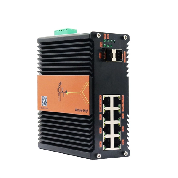
In this Cisco Tech Talk, learn how to view the optical module status on a Cisco switch using the Command Line Interface (CLI). This video demonstrates how to access the optical module status, check for any issues, and monitor the health of your network's optical components. Learn. When optical modules operate on a switch, it is usually necessary to read the module's internal information to understand its working status—such as connection status and real-time metrics like optical power and temperature. Additionally, identifying module information helps detect coding. This chapter describes how to configure the Optical Amplifier Module and Protection Switching Module (PSM). When you plan to replace a configured optical module with a different type of optical module, you must clear the configurations of the old module before you install the new module. By checking module health, compatibility, and digital diagnostics, you can quickly confirm correct installation, detect optical problems, and maintain accurate hardware. Small Form-factor Pluggable modules (SFP module) are the workhorses of modern network connectivity, enabling flexible fiber optic or copper links between switches, routers, firewalls, and servers. Whether you're upgrading bandwidth, replacing a faulty unit, or reconfiguring your topology, knowing.
[PDF]
The Huawei OEGD01N01 is an Optical Functional Module known for its robust functionality in networking environments. It is a 1000BASE-T-SFP Module featuring an RJ45 Electrical Module with auto-negotiation capabilities. Optical modules are widely used in switches, network interface cards (NICs), routers, and other communication devices. During use, reading optical module information helps understand its real-time operating status, enabling faster troubleshooting of link abnormalities. The following uses the. A switch must use optical or copper modules that have been certified for use on Huawei switches. Non-certified optical or copper modules cannot ensure transmission reliability and may affect service stability. Designed for optimal performance, it supports a longest transmission distance of. OLT is the world's first Terabit fiber access system. With the pending support for XG-PON1 (10Gbps downstream and 2. 5Gbps upstream data rates) technology, Huawei's MA5600T OLT is designed to provide even higher subscriber bandwidth in shared fiber splitter applications. Huawei's all-in-one fiber. TX/RX power test ensures that the optical power are within the thresholds; remove the aged optical module with power loss, and the fake module with counterfeit label. Huawei is not liable for any problem caused by the use of non-certified optical or.
[PDF]
This simple step resolves many issues with sfp optical transceivers in access switches and core routers. Test with a known-good module or patch cable. If the issue persists, suspect either the switch port or external fiber path. Read TX/RX power, bias current, voltage, and. Optical transceivers play a crucial role in modern data communication networks, enabling the transmission and reception of optical signals across fiber-optic cables. However, like any other electronic component, optical transceivers can encounter issues that may affect network performance. This guide. This guide provides a deep technical overview of how to troubleshoot sfp optical transceivers and other optical transceivers module types effectively in 2025. These compact devices convert electrical signals to optical signals and vice versa, enabling data transmission over fiber optic cables. We'll discuss how to identify the issue, possible causes of optical transceiver issues, troubleshooting steps, and. Have you ever experienced an unexpected network outage due to the failure of an SFP/SFP+ optical transceiver? Network outages can bring your ability to communicate and work to a halt, and your IT team will likely be frantically looking for a solution. It is important to understand how to.
[PDF]
Optical trap or "tweezers" is a device used to apply piconewton sized forces and make precise measurements on a scale of roughly one micron. It can be created by applying a precisely focused laser onto a dielectric material. Thorlabs' OTKB (/M) Modular Optical Tweezers provide users with a tool for trapping and manipulating microscopic-sized objects. These laser-based tweezers, or traps, have been employed in numerous biological experiments. Biological applications for optical tweezers include trapping viruses and. Our advanced optical trap generator based on ultra-fast AOD technology. Versatile and flexible optical trap manipulation designed for biological samples. Learn to calibrate the 20. Use calibration information to observe the rotation of E. coli bacteria, and determine the forces required to stop this rotation. Based on their design, Thorlabs has collaborated with the aforementioned authors to design an OTKB optical trapping kit that includes all necessary components and provides the same capabilities. Enclosed into a high-quality aluminum box and assembled onto the. Torr Scientific offers a range of magneto-optical traps (MOT) (also known as atom trap chambers) used as part of ultra-cold vacuum systems, to capture atoms for testing purposes. This is a chamber module, formed of low-magnetic permeability materials for use at ultra-low temperatures nearing.
[PDF]
Check the diagnostic information, which shows that the received optical power is low, with a threshold of -3 to -23. 01, currently at -22. Once it exceeds the threshold, an alarm will be triggered. Troubleshoot the link, and if the link is normal, replace the optical. Run the display interface transceiver verbose command in the user view to check whether the transmit optical power (Tx Power) of the interface is within the allowed range. If yes, collect alarm, log, and configuration information, and contact technical support personnel. If the optical module is. An optical module was faulty. Cause 2: Output Optical Power Too High. Services on the optical module may be affected, which may cause bit errors, error packets, or even service interruption. During use, reading optical module information helps understand its real-time operating status, enabling faster troubleshooting of link abnormalities. The following uses the. The International Photonics & Electronics Committee (IPEC) is an international standards organization that is committed to developing open optoelectronic standards and delivering strategic roadmap reports. IPEC focuses on standardizing solutions in optical chips, optical/electrical components, and. The optical module on the port generates an alarm. Often referred as I²C, I2C, IIC (Inter-Integrated Circuit), MDIO (Management Data Input/Output) or CMIS (Common Management Interface Specification), these serial bus.
[PDF]
A common test setup to evaluate Stressed Receiver Sensitivity involves measuring the Optical Modulation Amplitude (OMA) using a square wave, per the standard guidelines. Receiver sensitivity stands as a critical parameter impacting an optical transceiver's functionality. It denotes a module's capability to function in challenging environments and aids network operators in determining the system's maximum reach or link margin. These metrics provide insights into how well your transceivers perform under different conditions, ensuring seamless data transmission. Optical. Whether you're a network engineer validating new inventory or an integrator preparing for deployment, knowing how to test optical transceiver modules can save time, reduce failures, and ensure SLA compliance. Unchecked optical modules can cause: Testing ensures compliance with IEEE 802. 3 and MSA. In optical communication systems, sensitivity is a measure of how weak an input signal can get before the bit-error ratio (BER) exceeds some specified number. The standards body governing the application sets this specified BER. For example, SONET specifies that the BER must be 10 -10 or better. Why Fiber Optic Transceiver Testing is Important? Identify faults and failures: Transceiver testing helps in identifying any faults.
[PDF]
Optical modules typically have an electrical interface on the side that connects to the inside of the system and an optical interface on the side that connects to the outside world through a fiber optic cable. An optical module is a typically hot-pluggable optical transceiver used in high-bandwidth data communications applications. Composition of Optical Modules The optical module, known as Optical Transceiver in. The optical module serves as a crucial component in optical fiber communication systems, operating at the physical layer, which is the lowest layer in the OSI model. Its primary function is to achieve optoelectronic conversion by converting electrical signals into optical signals and vice versa. Operating at the physical layer of the OSI model, optical modules are core devices in optical.
[PDF]
The main trade show for the large optical module industry is the Optical Fiber Conference (OFC), that is held annually in southern California. Other prominent shows for the industry include ECOC in Europe and FOE in Japan.
[PDF]
First, inspect the optical module appearance for physical damage, cracks, missing components, poor solder joints, or burn marks. Next, compare voltage, resistance, and waveform parameters between a normal it and the suspected faulty one, both in powered and unpowered states. However, optical modules may become damaged or malfunction due to prolonged use or improper operation. In order to ensure the normal operation of the optical communication system, it is crucial to promptly inspect and repair damaged optical modules. This article will introduce some common methods. Optical modules in the application must have standardized operating methods, any irregular action may cause hidden damage or permanent failure. The primary causes of optical module failure are performance degradation due to ESD damage, and optical path discontinuity caused by optical. The optical module is faulty or not securely installed. The device management or driver software has a bug. Use an optical power meter to check whether the transmit optical power of the optical module is normal. However, during installation and daily operation, various issues may arise. Therefore, understanding common optical module.
[PDF]
This report studies the global Optical Module PCB Board production, demand, key manufacturers, and key regions. Optical Module PCB Board by Application (Optical Receiving Module, Optical Transmitting Module, Optical Transceiver Module, Optical Forwarding Module), by Types (Single-layer PCB, Double-layer PCB, Multi-layer PCB), by North America (United States, Canada, Mexico), by South America (Brazil. Dongshan Precision plans to acquire Taiwan's Source Photonics for up to $850 million to expand its optical communications business. The deal, which aims to integrate Source Photonics' vertically integrated operations and high-speed optical module capabilities, is pending approval from Taiwan's. The Optical Module PCB Board market is experiencing significant growth, driven by the increasing demand for high-speed data transmission in various industries, including telecommunications, data centers, and consumer electronics. These printed circuit boards (PCBs) play a vital role in connecting. The global Optical Module PCB Board market size was US$ million in 2024 and is forecast to a readjusted size of US$ million by 2031 with a CAGR of %during the forecast period 2025-2031. The Optical Module PCB Board Market is expected to grow from 2,490 USD Million in 2025 to 5. 8 USD Billion by 2035. This report is a.
[PDF]
This guide breaks down practical differences—core geometry, wavelengths, connector types, performance limits, cost trade-offs, and ideal use-cases—so you can pick the right optical modules with confidence. SFP (Small Form-factor Pluggable) is a compact, hot-swappable module used in network devices such as switches, routers, and servers to provide network connectivity and is widely used in network communications. By using different interfaces and single-mode or multimode fiber depending on the. Multimode and Singlemode optical modules differ in terms of fiber type, transmission distance, cost, and application scenarios. Understanding these differences is the first step in selecting the right module. Multimode Optical Modules: These modules are typically used for shorter transmission. Multimode SFP module offers a practical solution for short- to medium-range 100G transmissions, particularly in high-density environments where performance, compatibility, and cost control are equally critical. At the end of the day, they answer one simple question: How much bandwidth can this fiber handle, and how far can it go? “OM” stands for Optical Multimode, which is a classification system for multimode fiber.
[PDF]