The price per foot includes the fiber itself, connectors, and basic installation factors, with main drivers being cable type, distance, and any required conduit or termination hardware. This article outlines cost expectations, price ranges, and practical savings. Fiber-optic cable materials typically cost $1 to $6 per linear foot, depending on fiber count and cable type. Commercial building installations with 100-200 network drops generally range from $15,000 to $30,000. Single-mode fiber costs less per foot than multimode fiber, but it requires more. Typically, per drop fiber cabling prices range from $250 – $1000 per drop depending on the type of fiber (OM2, OM3, OM4, or OM5), multi or single mode, PVC or plenum, average drop length, and also the number of fibers in each cable. This. Whether you need singlemode, armored, or indoor plenum, this guide gives you the exact cost per foot of fiber optic cable — including installation — so you can budget without guesswork. Data aggregated from Q1 2026 contractor invoices across Texas, Ohio, and North Carolina. The installation type you choose and the layout of your property determine the total labor and materials needed for your project. Cost for fiber cabling projects.
[PDF]
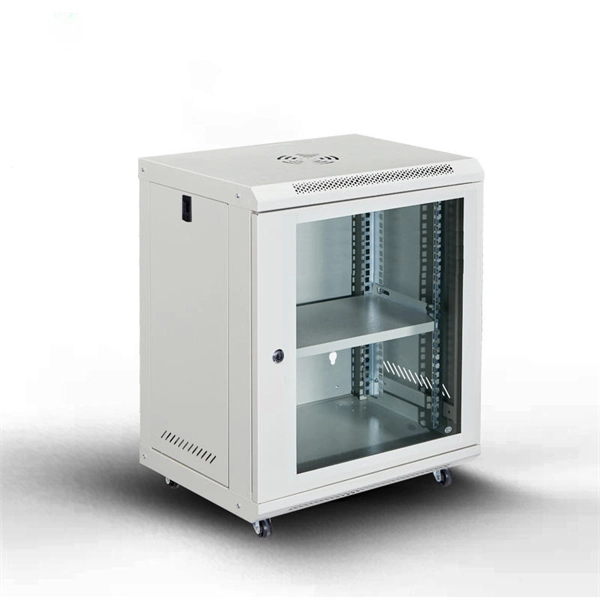
Find reliable fiber ODF with price from top suppliers. Shop our collection of high-quality patch panels and distribution frames for communication networks. Optical Distribution Frame (ODF) is integrated components in any fiber management system to handle termination and cross-connection of cables. Pre-terminated ODFs with cables are pre-installed with connectors and cable for quick and easy installation. Units with pre-terminated cables offer. Streamline your fiber connectivity with our premium Fiber Optic Patch Panels and ODF systems. Designed for reliability and ease of use, our rack-mount and wall-mount solutions provide the perfect environment for splicing, terminating, and managing your critical fiber optic connections. It is a device that splices, distributes, and splits optical fibers and provides protection and management of optical fibers. Growth is driven by investments in hyperscale data centers and fiber-to-the-x (FTTx) networks. Asia-Pacific remains the manufacturing and consumption hub, with significant activity also in North America and Europe. Innovation is reshaping product offerings and, consequently, pricing tiers.
[PDF]
This guide covers everything: what fiber optic pigtails are, how they differ from patch cords, which connector and polish type to specify, how to choose between mechanical and fusion splicing, and the real-world applications where pigtails are the right call. This article compares fusion splicing and pre-terminated solutions on these terms, and reviews what's required in a hyperscale ODF in order to scale up to 5,000+ connections in a single frame. Fusion splicing vs connectorization: what's the best choice for a hyperscale ODF? The physics and. Fiber optic joints or terminations are made two ways: 1) splices which create a permanent joint between the two fibers or 2) connectors that mate two fibers to create a temporary joint and/or connect the fiber to a piece of network gear. Either joining method must have three primary characteristics. There are two primary techniques for terminating fiber optic cables: Splicing: Joining two fiber optic cables permanently. Connectors: Attaching removable connectors for quick and flexible connections. Fiber splicing is the process of permanently joining two optical fibers end-to-end. This blog will delve into the nuances of each method, comparing their costs, labor efficiency, network performance, and more, to help you decide which splicing technique is best suited for your needs. Fusion splicing involves heating the fiber ends and fusing them together, while mechanical splicing uses tubes, V-grooves, or other guides to.
[PDF]
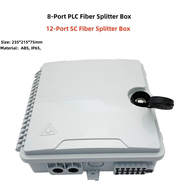
ODF, Splitter Distribution Box, and Fiber Terminal Box are not interchangeable, but complementary components of an FTTH network. ODF ensures efficient backbone fiber management in central offices. In FTTH, FTTB, and other fiber access networks, terms such as Fiber Optic Termination Box, Fiber Distribution Box (FDB), and ODF (Optical Distribution Frame) are frequently mentioned. Although all three are related to fiber connection and management, their installation locations, functional roles. To realize the connection of fiber optic cable, we often need to use ODF (optical distribution frame), fiber optic termination box ( rack mount fiber optic patch panel, fiber outlet), fiber distribution box for fiber management in the fiber optic link. Although they all belong to the optical distribution and management system, their. An Optical Distribution Frame (ODF) is a dedicated unit designed to organize, terminate, and interconnect fiber optic cables. It brings together fiber splicing, patching, and cable routing in a single structure, while shielding sensitive connectors and splices from mechanical stress or. Although both appear to "manage fiber," they serve very different roles in a modern optical network. This 2026 expert guide explains the functions, placement, structure, and application scenarios of ODFs and fiber patch panels-and includes a deep engineering FAQ that resolves real-world deployment.
[PDF]
An ODF is a centralized platform designed for terminating, cross-connecting, and managing optical fibers. It ensures fiber management is structured, minimizes signal loss, and provides accessibility for maintenance and future expansion. In modern data centers and enterprise networks, Optical Distribution Frames (ODF) serve as the backbone for organizing, terminating, and managing fiber optic connections. This article explores the types, components, applications, installation, and maintenance best practices, providing a. Network managers need a better solution, one that supports rapid deployment, plug-and-play connectivity and high density—all while maximizing the usable density and long-term value of the fiber network. With a compact, modular frame, high-density plug-and-play elements, and full-frontal access, the. Optical Distribution Frames (ODF) are indispensable components in optical communications networks. They provide efficient fiber optic management, connectivity, and protection. As data centers, enterprises, telecom operators, and smart-building infrastructures deploy increasingly dense fiber links, ODFs provide the structured. This complete guide explores everything you need to know about ODFs — from their structure, types, and key components, to installation best practices and modern design trends.
[PDF]

This is a walkthrough for the TASK Master side mission in Borderlands 4. Read on to follow the objectives and clear the mission, as well as how to replace power core. TASK Master is part of a questline that starts with The Kairos Job. A core switch in networking serves as the high-capacity backbone, italic centralizing data flow and ensuring efficient communication between different network segments. Simply put, it's the kingpin that keeps your network humming. You may also want to know: Can a Nintendo Switch Play DS Games? ·. To prevent electrostatic damage (ESD) to electronic components, you must be sure that you are grounded while handling electronic components. Components include, but are not limited to, all switch modules. Connect the switch to the facility earth ground. Attach an ESD wristband to your arm and be. Unless you power on layer 3 switch; specifically 3650, you will not be able to configure it or even access the command line interface (CLI). In this post, I will show you how to power on Layer 3 switch in packet tracer; both the steps you need to take and a video demonstrations of the process Here. In such high-capacity ethernet networks, switches are crucial as they direct data and transmit signals to the addressed devices. There are different types of enterprise switches that perform various roles in these layer-based or hierarchical ethernet networks. Complete The Kairos Job, Free for the TASKing, and TASK and Ye.
[PDF]
The layer 2 switches collect the data from core switches, identify the type of data packet and the address of the access device. Selective routing and switching take place at the distribution layer. Those new distribution switches will have L3 redundant connections to the CORE switches running EIGRP so this will provide us high availability and load balacing. The connection between these distribution switches is going to be a L3 link (Cisco recommendation) in order to summarize our networks to. · Layer Positioning: The data link layer (Layer 2) of the OSI model, realizing local forwarding of data frames based on MAC addresses. · Core Task: Establishing direct interconnections between devices within a local area network to ensure efficient communication within the same network segment. ·. Layer 2 Switch is a form of Ethernet switch that switches packets by looking at their physical addresses (MAC addresses). These switches operate at the data-link layer (or layer 2) of the Open Systems Interconnection (OSI) reference model. At Layer 2, edge switches use media access control (MAC) addresses to manage traffic within a local area. The core layer is the backbone of the network. The distribution layer connects the access layer to the core layer. When designing a campus LAN, you may. Physical Layer - Physical layer of TCP/IP model is responsible for physical connectivity of two devices. It contains multiple input/output ports.
[PDF]
This document is intended for network engineers responsible for switch configuration and management. You should be familiar with basic Ethernet knowledge and have extensive experience in network deployment and management. The symbols that may be found in this document are defined. S7700&S8700&S9700&S12700&S16700 Series: Access product manuals, HedEx documents, product images and visio stencils. Symbol Description Indicates a potentially hazardous situation which, if not avoided, could result in equipment damage, data loss, performance deterioration, or unanticipated results. NOTICE is used to address practices not related to personal injury. Supplements the important information in the. Page 1 Quidway S7700 Smart Routing Switch V100R006C00 Configuration Guide - SPU Issue Date 2011-07-15 HUAWEI TECHNOLOGIES CO. Page 2 All other trademarks and trade names mentioned in this document are the property of their respective holders. Notice The purchased products, services and. line starting with the # sign is comments. In device configuration, use the existing interface numbers on devices. To ensure device security, use ciphertext when configuring a password and change the password periodically.
[PDF]
Quick Answer: To check CPU utilization on a Cisco switch, use the command “show processes cpu” in the CLI. This displays current CPU load, CPU usage history, and process-specific details, aiding in network performance troubleshooting. The CPU becomes too busy when either an IOS process consumes too much CPU time or the CPU receives too many packets from the switching hardware. When either of these two CPU consumers requires the CPU resource to the detriment of the other, then the CPU is too busy. For instance the CPU is. High CPU utilization on Cisco switches can lead to degraded network performance, packet loss, and even switch failures. Identifying and troubleshooting the root cause of high CPU usage is essential for maintaining a healthy network. In this article. I noticed that after having VLANs, ClearPass, spanning tree, and all other settings configured, that CPU util was just sitting at or above 85% on all these switches. I updated firmware to the latest version on all of them, but that didn't help. Problem analysis process 1. According to the switch logs, after searching for related processes, we can find that the. my switch core has high CPU usage every 3 minutes, switch logs attached. Do the outages/CPU spikes occur at the same time as the log entries appear such as : 00828 lldp:. Thank you, Fix the problem indicated.
[PDF]
MDC virtualizes one S7500X switch into multiple logical switches, enabling multiple services to share one core switch. The 1:N virtualization maximizes switch utilization, reduces network TCO, and ens.
[PDF]
A core switch is a crucial component of a network infrastructure that serves as the backbone of a network. It's a high-performance switch that provides high-speed connectivity between different network segments, which may include access switches, distribution switches, and routers. Engineered to aggregate massive volumes of data from distribution switches, it provides ultra-low latency and maximum throughput to ensure uninterrupted routing and packet. It's more than just a switch; it's the central nervous system of your network infrastructure. Its primary function is to rapidly forward data packets between. Professional networks are structured using a three-tier hierarchical model to ensure scalability and efficient traffic management. This model divides the network into three functional layers: the Access Layer, the Distribution Layer, and the Core Layer. The Access Layer sits at the edge, using. Core switches are the focal point for traffic control between access and distribution switches. They perform a vital function in ensuring the network's reliability and stability because they are in charge of routing data across the network infrastructure in a reliable and timely manner. They operate at the data link layer (Layer 2) or the network layer (Layer 3) of the OSI (Open Systems Interconnection) model, facilitating the communication of devices on a network by receiving, processing.
[PDF]
In this video we will learn how to configure cisco core switch active active using HSRP step by step. In this LAB we practice on creating vlan, distribute vlan to other switch in our network, creating interface vlan and assign IP address for layer 3 routing, and. more. Follow these simple best practices to set up a new network switch. And this process is a little more advanced than, say, setting up your home Internet or even a plug-and-play type switch. But, with the right guidance. Although a Cisco switch is a much simpler network device compared with other devices (such as routers and firewalls for example), many people have difficulties to configure a Cisco Catalyst Switch. Unlike other lower class switch vendors (which are plug-and-play), the Cisco switch needs some. Looking to configure a Cisco switch for the first time? If the answer is YES, you're in the right place. You're going to configure: SSH access with local AAA authentication. Cisco switches are used in both small and large networks to manage traffic, control access, and provide the infrastructure for local area networks. What configuration does a core switch have? EXTENSIBILITY SHOULD INCLUDE TWO ASPECTS 1. The slot is used to install various function modules and interface modules. more In this video we will learn.
[PDF]
The generally accepted and code-compliant height for switches is typically 48 inches (4 feet) from the finished floor to the top of the switch box. This standard helps ensure accessibility and consistency across installations. While the National Electrical Code (NEC) doesn't specify a mandatory standard outlet height for most general-use receptacles, established industry best practices and accessibility laws provide clear guidance. The NEC (Article 210. 52) specifies where receptacles must be placed (spacing along walls, required. The commercial electrical code requires switches at 42 to 48 inches and receptacles at 18 inches above finished floor in most applications. This height is an ergonomic choice, aligning well with the average reach.
[PDF]
Lasers, modulators, and photodiodes form the core architecture of optical transceivers, enabling light-speed communication across global networks. Lasers generate the optical carrier. Modulators encode digital information. An optical transmitter is a crucial device used in fiber optic communication systems. Its primary function is to convert electrical signals into optical signals It involves modulating electronic system data and transforming it into light pulses using a laser or LED, and sending the pulses through. The optical transmitter and the optical receiver are the core components that enable this process, forming the electronic-to-optical and optical-to-electronic gateways necessary for modern, high-capacity data transmission. It takes data from an electronic system, uses a laser or LED to modulate that data into pulses of light, and then sends those pulses down the fiber. Together, lasers, modulators, and. At the core of a fiber optic system is the optical fiber – a flexible, transparent strand of glass, thinner than a human hair. Optical fiber is formed by drawing glass or plastic to a diameter slightly thicker than that of a. What are the main elements of an optical transmitter? Data decoder/demodulator, electrical interface, detector, optical interface.
[PDF]
Enables IP routing between VLANs, subnets, and security zones, with advanced routing protocols. Includes dual power supplies, hot-swappable modules, link aggregation (LAG), and support for HSRP/VRRP. Modular chassis or stackable designs make it easy to scale as your network. A core switch is the primary switch installed at the backbone of a layered or hierarchical network. Engineered to aggregate massive volumes of data from distribution switches, it provides ultra-low latency and maximum throughput to ensure uninterrupted routing and packet. A core switch is the backbone of a large-scale network, designed to handle massive volumes of traffic with ultra-low latency and maximum reliability. It is mainly responsible for high-speed forwarding and management of large amounts of data traffic from various aggregation layer switches. It usually has powerful processing capabilities, high. A core switch in networking serves as the high-capacity backbone, italic centralizing data flow and ensuring efficient communication between different network segments. Simply put, it's the kingpin that keeps your network humming. You may also want to know: Can a Nintendo Switch Play DS Games? ·. While both core and normal switches play crucial roles in maintaining efficient data flow, their functionality and applications vary significantly. What Are Core and Normal Switches? A core.
[PDF]