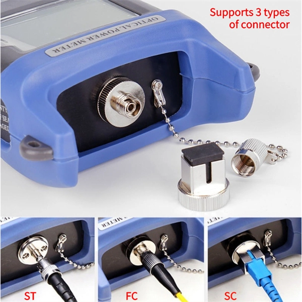
An optical power meter (OPM) works by converting light energy into electrical energy using a photodiode sensor. When light from a fiber optic cable hits the sensor, it generates a small electrical current related to the light's strength. Optical power meters are a key element in the optimization and maintenance of such optical networks and of their components. In this article, learn: What is an optical power meter? An optical power meter (OPM) measures the power levels of light signals in devices that transmit data or power using. An optical power meter (OPM) is a device used to measure the power in an optical signal. The term usually refers to a device for testing average power in fiber optic systems. It measures the optical power transmitted through a fiber, helping to verify if the light signal is strong enough for communication. Beginners may find it complex, but understanding its function makes it. This article provides a comprehensive overview of optical power meters, instruments used to measure the power of light beams. It details the main components, including sensor heads and display units, and explains the two primary sensor technologies: robust thermal sensors for high powers and. A fiber-optic power meter is a quantitative measurement instrument, not a diagnostic tool by itself.
[PDF]
An optical power meter is an electronic device that measures the power of an optical signal. It helps engineers verify the performance of optical fiber systems, ensuring that the signal strength meets requirements, and is an essential tool for communication network maintenance and. An optical power meter (OPM) is a device used to measure the power in an optical signal. Other general purpose light power measuring devices are usually called radiometers, photometers, laser power meters (can be. An optical power meter (OPM) measures the power levels of light signals in devices that transmit data or power using light. The term "optical power meter" may sound generic, but in popular usage, it specifically implies a fiber optic power meter. For light power measurements outside the field of. Optical Power Meters (OPMs) are crucial instruments in the field of optical sensors and fiber optic communications. It provides an expert-curated supplier directory, buyer-focused technical background information, and structured selection criteria to support professional procurement decisions. It measures optical power directly, and it is also used in loss testing when paired with a stable light source.
[PDF]
Absolute optical power calibration of optical power meters, radiometers and photodiodes: From 350 to 1650 nm in 5 nm steps, power range +10 to -60 dBm / 10 mW to 1 nW, with least uncertainty of 0.06 dB.
[PDF]
Your AC unit won't turn on after a breaker trips, so check your fuse box and reset the breaker to repair an AC unit. Costs range from $130 to $3,000 to repair an AC unit, with average costs around $350 based on the repair. Use the information below to estimate how much electricity an appliance is using and how much the electricity costs so you can decide whether to invest in a more energy-efficient appliance. Simply connect any appliance to the Kill A Watt EZ, it will then assess how efficient each appliance really is. They were not intended to be prescriptive in terms of what people should build, but they do stipulate important dos and don'ts – many of which. Atomic Energy Act of 1954, secs. 11, 53, 63, 65, 81, 103, 104, 161, 170H, 182, 186, 223, 234, 274, 1701 (42 U. 2014, 2073, 2093, 2095, 2111, 2133, 2134, 2201, 2210h, 2232, 2236, 2273, 2282, 2021, 2297f); Energy Reorganization Act of 1974, secs. 5841, 5842); Low-Level. EPA and the Centers for Disease Control and Prevention (CDC) agree that there is no known safe level of lead in a child's blood. Taking action to reduce these exposures can improve outcomes. Lead is harmful to health, especially for children. On this page: General Information about Lead in Drinking.
[PDF]
Check the diagnostic information, which shows that the received optical power is low, with a threshold of -3 to -23. 01, currently at -22. Once it exceeds the threshold, an alarm will be triggered. Troubleshoot the link, and if the link is normal, replace the optical. Run the display interface transceiver verbose command in the user view to check whether the transmit optical power (Tx Power) of the interface is within the allowed range. If yes, collect alarm, log, and configuration information, and contact technical support personnel. If the optical module is. An optical module was faulty. Cause 2: Output Optical Power Too High. Services on the optical module may be affected, which may cause bit errors, error packets, or even service interruption. During use, reading optical module information helps understand its real-time operating status, enabling faster troubleshooting of link abnormalities. The following uses the. The International Photonics & Electronics Committee (IPEC) is an international standards organization that is committed to developing open optoelectronic standards and delivering strategic roadmap reports. IPEC focuses on standardizing solutions in optical chips, optical/electrical components, and. The optical module on the port generates an alarm. Often referred as I²C, I2C, IIC (Inter-Integrated Circuit), MDIO (Management Data Input/Output) or CMIS (Common Management Interface Specification), these serial bus.
[PDF]
The most common causes of a fluctuating multimeter reading is due to a bad connection or loose wiring in the circuit. In order to investigate this possibility you will need to thoroughly inspect all of your connections and wires for any signs of oxidation, corrosion, fraying or. However, what happens when your multimeter starts behaving erratically, displaying fluctuating readings instead of stable values? This seemingly minor issue can lead to misdiagnosis, wasted time, and even potential safety hazards. Understanding the reasons behind a jumping multimeter reading is. The reading displayed on the meter is affected by factors like voltage drop across components in the circuit being tested. If this reading keeps jumping around unexpectedly it could indicate a problem in the circuit itself. Measuring Current: For current measurement, I switch the multimeter to the current setting. This method allows me to see how much current flows through. This guide delves into the various causes of multimeter fluctuations and provides practical solutions to ensure accurate. From fluctuating readings to unresponsive display screens, recognizing these common issues early on can prevent costly mistakes and potential hazards. These types of issues can often be fixed by replacing faulty wiring and securing.
[PDF]
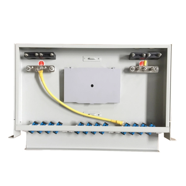
The most common and effective solution is the preformed tension clamp. This fitting consists of a set of helical rods that are wrapped around the cable, a thimble (clevis), and an extension link. The helical rods are designed to transfer the tensile load from the cable to the anchor. The function of the remaining cable rack is to store reserved optical cables, which are generally used on tensile towers (poles). There are two types: Inner button and outer disc. When the remaining cable rack is used for installation on the iron tower, it is equipped with two small splints. Additionally, adapters are available for the steel towers and steel and concrete poles. maintain alignment of and. ficing corrosion resistance. It is best suited to applications with moderate to low span ut increasing fibre strain. 3mm2 RRU Power cable. Without additional adapters, these clamps can provide sturdy, reliable, long-term support to systems. We manufacture a wide range of hardware fittings for OPGW Optical Ground Wire, including Suspension and Tension Assemblies, Down Lead clamps, Earthing Clamps, Splice Enclosure, Reinforcing Rods, Vibration Dampers, etc. Find many great new & used options and get the best deals for 5x Huawei Optical Cable Fixing Clamp 2x3 C Type Bracket Cable Clamp 27150086 at the best online prices at eBay! Free shipping for many products!.
[PDF]
Simply put, the output or transmit power (TX Power) is the strength of the signal that's leaving the device. This should fall within a specific range determined by the capabilities of the transmitter. Optical power is the degree of energy that comes from optical signals, which is one of the key parameters of a WDM system. The. In this section, we will learn how to do the following things: Determine the gain of a laser ampli er Find the threshold gain of a cavity Predict the output power of a laser Determine the output mode of the laser Unless otherwise stated, steady state ( d = 0) behavior may dt be assumed. When the signal received is outside of the range, there is a. When it comes to evaluating the performance of an optical transceiver, two key factors come to the fore: Output power (TX Power) and Receiver Sensitivity (RX Sensitivity). An understanding of these concepts is pivotal to establishing an effective and efficient optical network. This comprehensive. As an essential component of optical fiber communication, optical modules are optoelectronic devices that facilitate the conversion between optical and electrical signals during the transmission process. Transmitter power characterizes the average optical power output from the laser under rated conditions, while receiver sensitivity indicates the minimum.
[PDF]
Need some clarification about NEC 770. 47 (B), it says that the direct buried conductive fiber optic cable shall be 12 in (300 mm) away from the power cables. Separating high-voltage power cables from low-voltage communication cables is a fundamental requirement in any electrical installation. This practice is mandatory for two distinct reasons: ensuring the safety of the structure and its occupants, and preserving the integrity of sensitive data. Maintaining proper separation between power, data, and limited energy cabling is foundational to system performance, safety, and code compliance. Separation isn't just an EMI precaution — it protects signaling, reduces rework, and ensures pathways meet inspection expectations across risers. TECHNICAL GUIDELINE July 30, 2020 TG030 Rev. 4 Pathway Separation Between Telecommunication Cables and Power Cables Communications cables are, by design or necessity, often installed in close proximity and/or in the same pathway as power service cables. The electrical energy of the power cables can. This standard titled “Commercial Building Standard for Telecommunications Pathways and Spaces” is a joint publication of ANSI/TIA/EIA. Its current version (ANSI/TIA/EIA/-569-B) was published in October 1, 2004 and describes EMI aspects in Article 10. ca with numerous contributions by others. "UTP Separation Guidelines From EMI Sources". The values are the same as the cabling pathways standard, EIA-569, table 4.
[PDF]
Full Technical Specifications: Explore our complete range of directional and dual directional couplers, featuring ultra-wideband operation from 0. This catalog details models with coupling values from 5 dB to 50 dB and power ratings up to 500 Watts. How does 6W market outlook report help businesses in making decisions? 6W monitors the market across 60+ countries Globally, publishing an annual market outlook report that analyses trends, key drivers, Size, Volume, Revenue, opportunities, and market segments. This report offers comprehensive. IPP's directional couplers offer some of the widest bandwidths at the highest power levels in the industry. These directional couplers are available in frequencies from 1 MHz., in power. Directional couplers are critical components in radio frequency (RF) and microwave systems, used to split or combine signals while maintaining signal integrity. These passive devices allow a signal to be directed from one port to another, with a portion of the signal being coupled to an auxiliary. We are an RF / Microwave / Wireless Telecom Manufacturer for component, modules and systems. We offer the widest range and best performance RF Directional Couplers and Quadrature Hybrids in the world, extremely aggressive pricing structure. RF directional couplers often. CorechTEK's Directional Couplers are engineered for precise RF and Microwave signal monitoring and power sampling. CorechTEK Couplers.
[PDF]
It performs error detection and alarm monitoring, serving as an essential tool for bit error testing in R&D and production of optical modules/ devices. Bit Error Ratio Tester is an instrument used to test and analyze bit error ratio in digital transmission systems, fiber optic communication systems, and digital microwave communication systems. Dimension Technology's BERT800 bit error tester series offers a comprehensive solution for testing and verifying high-speed optical transceiver modules. OPTELLENT is a provider of broadband test and measurement solutions for communications. The Company's test & measurement solutions are used in product development, manufacturing. As transmission rates continue to accelerate, accurately measuring bit error rates in optical modules is crucial to ensure reliable performance. There are three interchangeable slot boards which include QSFP, SFP+ and SFP ports separately. QSFP, SFP+ and SFP ports follow QSFP MSA, SFP+ MSA and SFP MSA. The user interface allows you to individually monitor bit error rate, error count and timer by connecting to PC via USB cable. In high-speed digital communication systems, even the smallest bit-level error can compromise performance, reduce efficiency, or lead to costly rework.
[PDF]
Use this selector tool to quickly identify the best power supply for your aerospace and defense ATE requirements. Explore engineer-authored content and a vast knowledge base with thousands of learning opportunities. Use 25+ X-Series applications to analyze, demodulate, and troubleshoot signals across wireless, aerospace/defense, EMI, and phase noise. With extra memory and storage, these enhanced NPBs run Keysight's AI security and performance monitoring software and AI stack. Achieve fast, accurate board-level. Fiber-optic switches control light paths within fiber optics, ranging from simple on/off types to complex matrix configurations like 64×64. Fiber-optic switches are optical switches in the context of fiber optics. They're a core component in fiber-optic networks, where data travels as pulses of light through glass fibers. This technology allows for high bit rate transmission to be switched between various optical lines. All of these optical switches are purely optical path, there is no optical to electrical to optical conversion. Click to jump to class of switch --- Provides a bypass of.
[PDF]
Mouser offers inventory, pricing, & datasheets for Copper Heat Sinks. Check each product page for other buying options. Need help? Copper heatsinks provide efficient heat transfer to keep your electronic components running at optimal temperatures. Discover the perfect cooling solution. Heat sinks are thermal management components designed to dissipate heat from high-power electronic devices and prevent overheating. Their core function is based on the principles of conduction, and convection, transferring heat from a heat source—such as a CPU, power transistor, or BGA package—to. Heat Sinks Cup Clips for TO-5 Case Style Semiconductors, 14. Heat Sinks Cup Clips for TO-5 Case Style Semiconductors, 14. A tariff of 10% may be applied if shipping to the United States. Due to copper's superior thermal conductivity (approximately 400 W/mK, nearly twice that of aluminum), copper heatsinks. Lot Of 2 Dell Copper Aluminum Heat Sink. Pulled From Clean Unit Sold As Scrap 100 PCS (8 Different Sizes) Heatsink Kit with Conductive Adhesive Tape, Alumi. Copper Aluminum Heat Sink Lot Sold As Scrap.
[PDF]
A WDM system uses a multiplexer at the transmitter to join the several signals together and a demultiplexer at the receiver to split them apart. With the right type of fiber, it is possible to have a device that does both simultaneously and can function as an optical add-drop. In fiber-optic communications, wavelength-division multiplexing (WDM) is a technology which multiplexes a number of optical carrier signals onto a single optical fiber by using different wavelengths (i., colors) of laser light. This technique enables bidirectional communications over a. WDM is a fiber optic transmission technique that leverages multiple light wavelengths to transmit data efficiently over a single medium. WDM technology employs different optical wavelengths, or colors, of laser light to multiplex several optical carrier signals onto a solitary optical fiber. Each. There are a lot of people who don't understand the difference between WDM and optical splitter. This allows multiple channels of data to be transmitted simultaneously. WDM technologies allow organizations to place equipment at either end of a fiber pair and combine multiple wavelength channels on a single fiber pair instead of using multiple separate fibers pairs for every separate service. The article explains the fundamental principle and its.
[PDF]
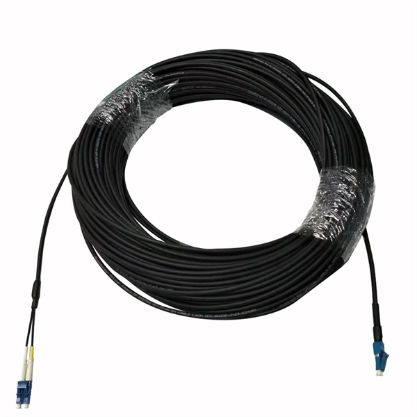
Evenly divide the cables connected to the storage device into two groups. Place the left group of cables into the troughs of the left cable tray, and the right group into those the right. When. In this article, we will explore four key aspects of dividing the wiring sequence and wiring of multi-core cables. This involves determining the optimal path for. Before attempting to split a fiber optic cable, gather the necessary tools and equipment: Fiber Optic Splitter: This device divides a single optical signal into multiple signals. Splitters come in various configurations, such as 1x2, 1x4, or 1x8, depending on how many splits are needed. Route optical fibers inside the cabinet along the posts on the sides of the cabinet and attach. In this video I will show you how to routing a fiber core in a joint enclosure. more In this video I will show you how to routing a fiber core in a joint. When it comes to understanding optical cables, it's essential to grasp the anatomy of these crucial components. An optical cable consists of three primary parts: the core, the cladding, and the protective sheath.
[PDF]