The SFP optical module is a standardized, modular assembly designed to be quickly installed or removed from a device's port without requiring the device to be powered down. This key feature—being hot-pluggable —is essential for simplifying network maintenance and minimizing downtime. SFP (Small Form-factor Pluggable) is a compact, hot-pluggable network interface module used to connect network devices (switches, routers, firewalls) to fiber optic or copper cables. It converts electrical signals into optical (or copper) signals and vice versa. An SFP transceiver acts as a compact, hot-swappable optical transceiver that. An SFP switch uses Small Form-Factor Pluggable (SFP) modules to form a network switch for high-speed connectivity between devices. These interchangeable modules support various media types, including copper or fiber-optic cables, providing flexible networking options based on specific requirements.
[PDF]
The mlxlink tool is used to check and debug link status and issues related to them. In order for mlxlink to function properly, make sure to update the firmware version to the latest. In this context, PHY can be understood as an optical module. When testing PRBS, there are 3 test nodes: MAC ----> PHY, PHY -----> MAC, and PHY ----- PHY. Signal testing can be performed through these 3 different nodes. and detection in MAC testing. Example: For device N9200-64DC, test ports. Qualcomm chips are now the core of high-speed optical modules for 5G networks, data centers, and enterprise interconnects. These modules leverage advanced signal processing, modulation, and high-speed interfaces to provide high bandwidth, low latency, and reliable performance. During use, reading optical module information helps understand its real-time operating status, enabling faster troubleshooting of link abnormalities. The following uses the. This article provides instructions on how to view the Optical Module Status on your switch through the Command Line Interface (CLI). The Cisco Small Business Series Switches allow you to plug in a Small Form-factor Pluggable (SFP) transceiver in their optical modules to connect fiber optic cables. mlxlink is. Could you please provide me some steps on how to enable ICMP debug on the 3850 to find the root cause of the problem? Thanks! Hello Eyad There are a couple of things that come to mind that may help you in your troubleshooting.
[PDF]
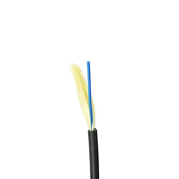
o In optical modules, "core" refers to the light-transmitting channel in the fiber. A 1-core module uses a single fiber core for data transmission, while a 2-core module uses two cores. o Think of a highway. A 1-core fiber is like a single-lane road—only one car (or. The secret lies in fiber optic technology, and understanding the basics—1-core, 2-core, Single Mode (SM), and Multi-mode (MM)—is key to mastering this field. Let's break down these terms in simple, clear language with practical examples. Definitions · 1-core vs. A. SFP (Small Form-factor Pluggable) is a compact, hot-pluggable network interface module used to connect network devices (switches, routers, firewalls) to fiber optic or copper cables. Think of it as the “translator” for your network equipment, converting electrical signals into optical signals. An optical transceiver is a modular device that serves as both a transmitter and a receiver (hence the name). In fiber optics, the data is sent in the form of light pulses or signals at high speeds and over long distances. The fiber optic transceivers convert the electrical input received from.
[PDF]
Frequent status changes from up to down or vice versa in the ports logged by the switch port syslog indicates a port flap. On a big industrial plant we've replaced an old HP switch with a brand new couple of C2960x switches in stack configuration and ever since then, every 6/8 hours or so, the two fiber optics links of switch #2 go down at once. These are connected to a ring of 3 similar other access switches, that. EX4650 2-switch virtual chassis, running version 19. 2, optic p/n 740-031981 (SFP+-10G-LR) is plugged into port xe-0/0/10 and connected to an ISP via single mode fiber. Nothing special is configured on the port, it is running at 10G speed, show interfaces diagnostics optics shows that it's. This article describes steps to diagnose the Continuous port flapping on a FortiSwitch. Verify Cable Connection: Ensure the cable is properly connected between the switch port and the end device. Run the command below on FortiSwitch multiple times and check the. Real head scratcher this morning that I'm hoping someone can help me with! The port on our core switch (HP A5500) that our Smoothwall box is connected to keeps going up and down. Port flapping, also known as link flapping, causes a switch port's state to fluctuate between up and down within concise periods of time. This instability caused by flapping ports affects network connectivity. Port flapping is a common network issue that can disrupt communication between devices and degrade overall network performance.
[PDF]

The short answer is no - RJ45 connectors are designed for electrical Ethernet signals, while fiber optics transmit light pulses through glass or plastic. However, modern networks often combine both technologies. A combo port, also known as an optoelectronic multiplexing interface, is a photoelectric composite port with two kinds of Ethernet interfaces (RJ45 port and SFP port) on an Ethernet switch. In other words, it is a compound port that can support two different physical layers and share the same. Optical ports on switches typically require the insertion of optical modules for data transmission over fiber optics. However, these two different physical ports can not be used at the same time. If you wake up the RJ45 port, the corresponding SFP port will. Ensuring seamless interoperability and compatibility between optical transceiver modules and network devices is crucial for maximizing network performance, reducing downtime, and controlling operational costs. This guide dives deep into the core aspects of optical transceiver compatibility, common. SFP (Small Form-factor Pluggable) is a compact, hot-pluggable network interface module used to connect network devices (switches, routers, firewalls) to fiber optic or copper cables. Think of it as the “translator” for your network equipment, converting electrical signals into optical signals.
[PDF]
Fiber optic switches utilize specialized ports such as XFP, SFP, CFP, SFP+, or QSFP+ to connect to fiber optic cables. These ports aren't directly compatible with the cables themselves; they require transceiver modules. SFP/SFP+ Modules: Small Form-factor Pluggable (SFP) modules are transceivers that connect the switch to the fiber optic cables. The choice between SFP and SFP+ depends on the network speed requirements, with SFP+ supporting higher speeds (up to 10 Gbps). Fiber Optic Patch Panels: These are used to. Choose an SFP module based on the fiber optic cabling that will be connected to the network switches. Always integrate duplex (two strand) fiber optic cabling or higher strand counts. The process requires understanding the type of fiber optic port on your switch and selecting the appropriate transceiver module. Always. I wish to connect (single mode) fibre optic cable to Fibre optic switch ( DIN-rail mounted) directly without using patchl panel or patch cords. I would also like to know what precautions should be taken during cable terminations. This is due to no or less space available for patch panels in my. The process of connecting fiber optic cables to network switches involves meticulous attention to detail and adherence to industry best practices to ensure reliable data transmission and seamless network connectivity. Before commencing the connection process, it is essential to ascertain the.
[PDF]
Use this selector tool to quickly identify the best power supply for your aerospace and defense ATE requirements. Explore engineer-authored content and a vast knowledge base with thousands of learning opportunities. Use 25+ X-Series applications to analyze, demodulate, and troubleshoot signals across wireless, aerospace/defense, EMI, and phase noise. With extra memory and storage, these enhanced NPBs run Keysight's AI security and performance monitoring software and AI stack. Achieve fast, accurate board-level. Fiber-optic switches control light paths within fiber optics, ranging from simple on/off types to complex matrix configurations like 64×64. Fiber-optic switches are optical switches in the context of fiber optics. They're a core component in fiber-optic networks, where data travels as pulses of light through glass fibers. This technology allows for high bit rate transmission to be switched between various optical lines. All of these optical switches are purely optical path, there is no optical to electrical to optical conversion. Click to jump to class of switch --- Provides a bypass of.
[PDF]
An optical module is a typically hot-pluggable optical transceiver used in high-bandwidth data communications applications. Optical modules typically have an electrical interface on the side that connects to the inside of the system and an optical interface on the side that connects to the outside world through a fiber optic cable. The form factor and electrical interface are often specified by an int. Electrical Interface TypesThere have been multiple variants of the electrical interface of optical modules that have been used over the years. The earliest forms of optical modules had an analog electrical interface. In the transmit dir. Many different forms of optical modulation and multiplexing have been employed in optical modules. The most common modulation technique historically has been or NRZ.
[PDF]
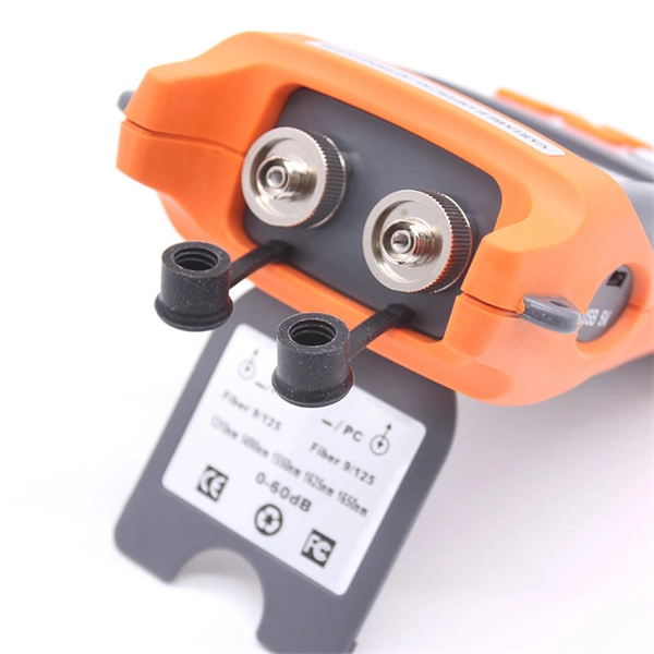
Use this worksheet to input values for all variables that will impact your system's performance. After entering your values, please ensure you click the 'Calculate Link Loss' button at the bottom of the page to generate your total link loss. Add connectors, splices, bends, and safety margin easily. See results instantly above the form, then adjust values. Choose a mode, then enter values and optional losses. All calculations use base-10 logarithms. mW must be greater than zero. Used only in measured attenuation mode. Length is needed. The power budget refers to the amount of fiber optic cable plant loss that a datalink (transmitter to receiver) can tolerate in order to operate properly. Sometimes the power budget has both a minimum and maximum value, which means it needs at least a minimum value of loss so that it does not. To detect whether the link runs properly, the following calculation should be performed. It is often the case to calculate the maximum signal loss across a given fiber link during optical cable installation. First, you should be aware of the fiber loss formula: The Total Link Loss = Cable. Therefore, it is very important to calculate the fiber loss and take appropriate steps. In order to get the most reliable results, an Optical Time Domain Reflectometer (OTDR) trace of the actual fiber connection should be completed. This will provide you with the real.
[PDF]
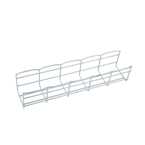
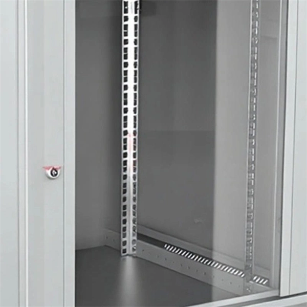
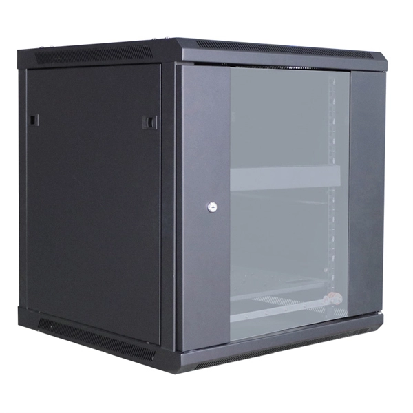
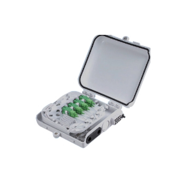
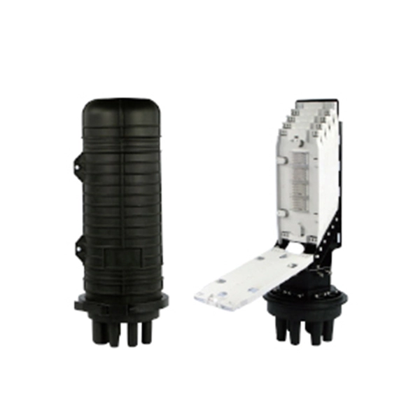
Through the adapter in the distribution box, the optical signal is led out by the optical jumper to realize the optical wiring function. An optical cable consists of three primary parts: the core, the cladding, and the protective sheath. The core is at the center of the optical cable and serves as the pathway for transmitting light signals. Surrounding the core is the cladding, which has a lower refractive index than the core. In the complex architecture of fiber optic networks, the Optical Distribution Frame (ODF) serves as the linchpin for organizing, protecting, and distributing optical signals. Whether in data centers, telecom central offices, or enterprise network rooms, ODFs enable efficient fiber management. The optical fiber distribution box is to protect the connection point where the optical cable is connected to the user end, so that the optical cable access point is stable, dustproof and waterproof. What is a fiber distribution box? 2. The. A fiber distribution box (FDB) functions as a central hub in fiber optic networks where the main cable is split into multiple individual fibers for distribution to end users. These boxes protect sensitive fiber connections from environmental factors while providing an organized framework for.
[PDF]
This review provides a comprehensive assessment of recent advances in polymer photonic sensing technologies, focusing on material systems, fabrication techniques, device architectures, and application domains. Waveguide technology represents a fundamental approach to controlling and directing electromagnetic waves, particularly in optical and microwave applications. This technology has evolved from basic optical fiber principles to sophisticated integrated photonic systems that enable high-speed data. Optical waveguides can be described as transparent structures which are more or less put onto solid carriers. In principle, they function just like fibers and are also described by the same parameters. However, there are also some fundamental differences: Waveguides are not produced ready-made by. The MZI structure consists of a polymer waveguide arm and a doped silica waveguide arm. Due to the opposite thermal optical coefficients of polymers and silica, the hybrid integrated MZI structure enhances the temperature sensing characteristics. The direct coupling method and side coupling method. Polymer-based photonic sensors are emerging as cost-effective, scalable alternatives to conventional silicon and glass photonic platforms, offering unique advantages in flexibility, functionality, and manufacturability. The design of the presented planar waveguides was realized on the bases of modified dispersion equation and was.
[PDF]
Need some clarification about NEC 770. 47 (B), it says that the direct buried conductive fiber optic cable shall be 12 in (300 mm) away from the power cables. Separating high-voltage power cables from low-voltage communication cables is a fundamental requirement in any electrical installation. This practice is mandatory for two distinct reasons: ensuring the safety of the structure and its occupants, and preserving the integrity of sensitive data. Maintaining proper separation between power, data, and limited energy cabling is foundational to system performance, safety, and code compliance. Separation isn't just an EMI precaution — it protects signaling, reduces rework, and ensures pathways meet inspection expectations across risers. TECHNICAL GUIDELINE July 30, 2020 TG030 Rev. 4 Pathway Separation Between Telecommunication Cables and Power Cables Communications cables are, by design or necessity, often installed in close proximity and/or in the same pathway as power service cables. The electrical energy of the power cables can. This standard titled “Commercial Building Standard for Telecommunications Pathways and Spaces” is a joint publication of ANSI/TIA/EIA. Its current version (ANSI/TIA/EIA/-569-B) was published in October 1, 2004 and describes EMI aspects in Article 10. ca with numerous contributions by others. "UTP Separation Guidelines From EMI Sources". The values are the same as the cabling pathways standard, EIA-569, table 4.
[PDF]
These OLT products facilitate users with high-speed data transfer, scalability, and reduced latency. In addition, there are also some drawbacks to these OLT products, such as high cost, difficult installation, and maintenance needs. Choosing between a small-capacity and a large-capacity OLT directly affects the scalability, cost, and overall efficiency of an FTTH deployment. This article compares small-capacity and large-capacity OLTs in terms of performance, design, and use cases, helping ISPs and network operators choose the. At the heart of a point-to-multi-point or passive optical network (PON) is the optical line terminal (OLT). Modern OLTs offer communication service providers (CSP) the ability to launch multigigabit services to tens of thousands of subscribers from a single location or just ten. Fiber-to-the-home. In the architecture of modern Fiber-to-the-Home (FTTH) networks, one piece of equipment stands as the undeniable command center: the Optical Line Terminal (OLT). It is the bridge between your core network and the thousands of end-users craving high-speed data, voice, and video. This pillar page is. Optical line terminals, OLTs, are a type of hardware device that serves as the terminal point for passive optical networks (PONs). Thus, it's an important part of fiber networks that transforms electrical signals between the ISP or service provider and the subscriber.
[PDF]
SFP optic modules change electrical signals into optical signals. This helps data move fast and far. You can upgrade them without turning off your network. An SFP (Small Form-factor Pluggable) is a compact, hot-pluggable transceiver module that allows networking equipment — including switches, routers, servers, and media converters — to support different physical media, such as optical fiber or copper, without replacing the host hardware. This modular. A small form-factor pluggable, or SFP optic module, helps connect network devices fast. SFP modules work in many network. SFP optical modules are the unsung heroes of fiber networking—the essential interface that converts electrical signals from network equipment into optical signals for transmission over fiber optic cable, and vice-versa. Think of it as the “translator” for your network equipment, converting electrical signals into optical signals. In the era of 5G, AI, and high-speed data centers, optical modules serve as the core bridge for converting electrical signals to optical signals (and vice versa), enabling fast, reliable data transmission across networks. In modern fiber optic networks, speed and stability depend on how efficiently data moves between devices. One small but essential component that makes this possible is.
[PDF]
Top 10 Fiber Optic Cable Manufacturers in 2025: Who to Choose & Why? Here's an updated list of the best fiber optic cable manufacturers, with FS and PHILISUN among the leaders driving innovation and connectivity worldwide. Based on 2025 rankings from industry sources like Owire and TSCables, the top manufacturers are evaluated on market share, innovation, and global reach. This list incorporates leading players, including Dekam-Fiber, Corning, Prysmian, and CommMesh, which stand out for their contributions to. With the global fiber optic cable market valued at $13. 92 billion and growing at 10. 46% annually, choosing from the best fiber optic manufacturers ensures your business infrastructure meets current demands and future scalability requirements. Selecting the right fiber optic company is the first critical step in. This updated list ranks the 20 largest fiber-optic cable companies worldwide and summarizes what each vendor is best known for—core product lines, regional strengths, and typical project fit. Use it as a fast shortlist when planning new FTTH/FTTA or data-center builds. 80% during the forecast period (2023-2032). This expansion is driven by surging demand for high-bandwidth networks, 5G.
[PDF]