Standards for pigtail loss
Guidelines On What Loss To Expect When Testing Fiber Optic Cables
All three of these methods are approved in many standards, but it is important to realize they will give different loss readings due to the connections included when making the 0dB reference measurement.
Fiber Optic Testing Standards
A uni-directional test will be conducted on all pigtail splices with no greater than a .8 dB loss accepted. Any loss higher than a .8 dB after 5 repeated attempts results in the replacement and re-splicing of
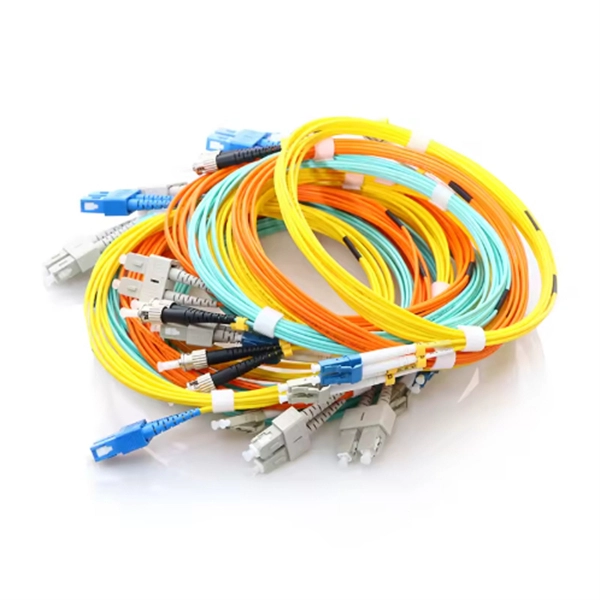
FIBER OPTIC SC FIBER OPTIC PIGTAIL, SIMPLEX SYSTEM
LINK fiber optic pigtail support application such as 25/40/50/100/200/400Gbps Ethernet, IEEE802.3ae 10G Ethernet, IEEE802.3z Gigabit Ethernet, IEEE802.3u Fast Ethernet, 52/155/622Mbps, 1.2Gbps
Fiber optic connector insertion loss
There are generally three methods for testing the insertion loss of optical fiber connectors: benchmark method, substitution method, and standard jumper comparison method.
Guidelines Corning Recommended Fiber Optic Test
important. The OTDR trace can be used for cable acceptance, splice and connector loss, documentation, troubleshooting, fault location, optical return loss, and to measure the length of PM
Guidelines On What Loss To Expect When Testing
All three of these methods are approved in many standards, but it is important to realize they will give different loss readings due to the connections included when
NR/L3/TEL/30162 ISSUE 3
This standard sets out the specific requirements and parameters for jointing, terminating and site acceptance testing of optical fibre cables that comprise, or connect to, Network Rail''s optical fibre
Optical Return Loss Measurement
ORL is measured according to the characteristics of components such as cables, patch cords, pigtails, and connectors as well as on an end-to-end network ORL level.
The FOA Reference For Fiber Optics
Many international standards do not allow using only an OTDR to measure the loss of an installed cable plant. Instead insertion loss testing using an OLTS or source and power meter are required.
Improving Connector Loss and Splice Loss OTDR Measurement
Nonetheless, as this paper demonstrates, an OTDR of sufficiently high resolution and dynamic range, and depending somewhat on the pigtail lengths, can accurately measure the connector loss and
Fiber Pigtail Kits
Multimode and single-mode pigtail kits shall be compliant with ANSI/TIA-568.3-E. Standard insertion loss shall be a maximum of 0.25 dB and low loss shall be a maximum of 0.15 dB for multimode and
Frequently Asked Questions
- Mi Home Dimming Module
- Relay protection secondary terminal block
- Sc pigtail components
- Latvia makes bulk purchase of OSFP Optical Optical Components
- How many vertical shaft cable tray supports are there per floor
- Intelligent Delay Fiber Optic Sensor
- Fireproof board and fireproof cable tray accessories
- 2020 Optical Cable
- Courtyard electrical distribution box label
- Working principle of relay protection maintenance pressure plate
- Power Supply Company Relay Protection Team
- Contact information for outdoor standard fiber optic cables
- Kenya Optical Receiver
- Price List for Installing Mobile Optical Cables
- Cable tray material for computer room
- Tunisian vertical shaft cable tray manufacturer
- How to tie wires when installing a distribution box
- Dubai Cable Tray Elbow Manufacturer
- How much does a solar cable tray cost in Palau
- Relay protection overload factor
- SC APC Fiber Optic Connector G 654 E vs Wireless CIF Price
- Norwegian Cast Busbar Prices
- Fiber optic patch cord itcom
- How to install a concealed wiring distribution box
- Ethiopia Molded Cable Tray Price Quote
- Brunei DC Distribution Box Custom Factory
- Original Honduran cable tray brackets
- Malta Professional Cable Trays
- Large commercial power distribution box obstruction
- Enterprise-grade optical router EML
- Where is the busbar compartment of the high-voltage switchgear
- Warranty for 400G Active Optical Devices
- Fiber optic splice box inlet line
- Where can I find cheap mesh cable trays
- Internal and external grounding of the distribution box