The price per foot includes the fiber itself, connectors, and basic installation factors, with main drivers being cable type, distance, and any required conduit or termination hardware. This article outlines cost expectations, price ranges, and practical savings. Fiber-optic cable materials typically cost $1 to $6 per linear foot, depending on fiber count and cable type. Commercial building installations with 100-200 network drops generally range from $15,000 to $30,000. Single-mode fiber costs less per foot than multimode fiber, but it requires more. Typically, per drop fiber cabling prices range from $250 – $1000 per drop depending on the type of fiber (OM2, OM3, OM4, or OM5), multi or single mode, PVC or plenum, average drop length, and also the number of fibers in each cable. This. Whether you need singlemode, armored, or indoor plenum, this guide gives you the exact cost per foot of fiber optic cable — including installation — so you can budget without guesswork. Data aggregated from Q1 2026 contractor invoices across Texas, Ohio, and North Carolina. The installation type you choose and the layout of your property determine the total labor and materials needed for your project. Cost for fiber cabling projects.
[PDF]
Abstract: Detecting partial discharges in cable joints is critical for timely defect identification and reliable transmission system operation. The electric field distribution of the optical fiber-implanted cable joint was simulated, followed by electrical performance tests, demonstrating that optical fiber implantation had a negligible effect on the electrical properties of the cable joint. A platform utilizing Mach–Zehnder–Sagnac. The results show that the average sensitivity of the sensor in the 10 kHz–80 kHz range is 71. 0 dB higher than that of the piezoelectric transducer, with a maximum signal-to-noise ratio of 65. To improve the long-term reliability and sensitivity of the sensing system, a novel method for cable joint monitoring based on implanting optical fibers. However, there is an industry gap in the literature about the highly sensitive fiber optic-based PD solution based on the acoustic emission principle. This paper aims to fill such an industry gap. In this paper, the fiber optic-based PD sensing (OptiFender) technology is applied to monitor the PD.
[PDF]
Discover the key differences between optical fiber cables and copper cables. OPTRAL analyzes the advantages and disadvantages to enhance connectivity. Optical and copper interconnection technologies represent two distinct approaches to data transmission, each with its own advantages and limitations. While fiber optics dominate in performance, copper retains its technical and economic justification. But how do you decide which one is best suited for your needs? This article delves into the technical comparison between copper and fiber optic cables. When it comes to modern data transmission, Fiber Optic cables and Copper Cables play pivotal roles in ensuring seamless connectivity. What Are Fiber Optic Cables? Fiber Optic cables function by transmitting data in the form of light pulses through optically pure glass fibers. These fibers are. “Fiber offers multiple technical advantages, including exceptional bandwidth, low attenuation and distortion over long distances, reduced bulk, as well as isolation from electromagnetic interference (EMI) and electrostatic discharge (ESD). ” Let's explore the characteristics, advantages, and. The two core material technologies used in almost all cables are fiber optic, and copper wiring. Whether you're looking at an HDMI cable, a USB cable, Ethernet patch cable, or any other kind of network of data transmission cabling, they are all built using copper or fiber optic internal wiring.
[PDF]
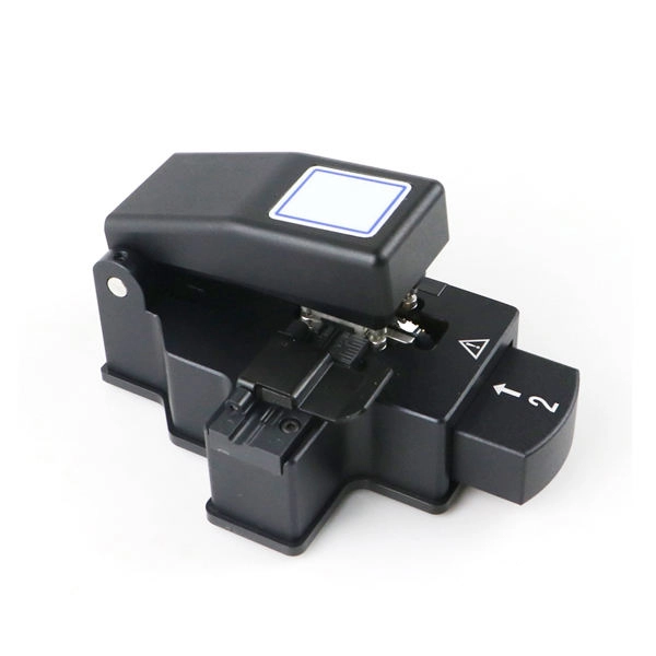
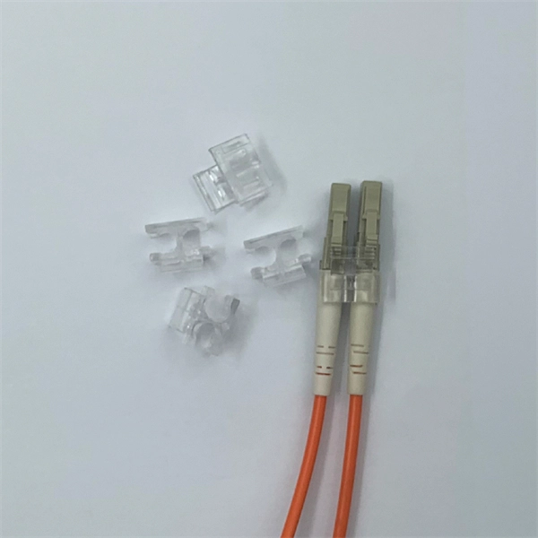
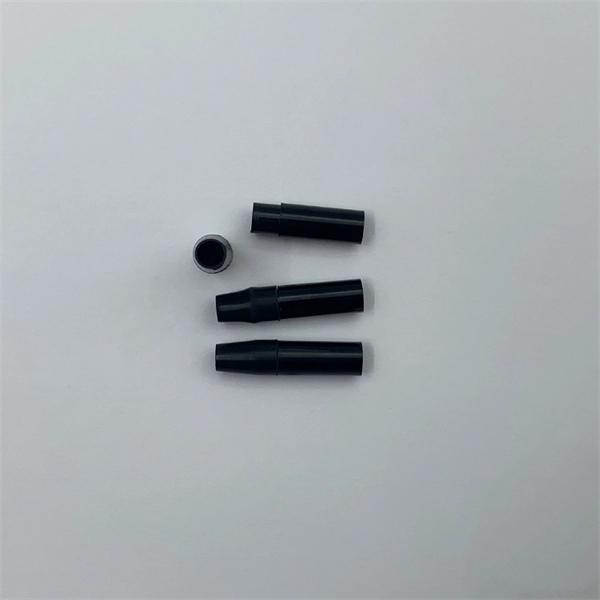
Get the wrong connector type, the wrong polish, or skip proper fusion splicing technique—and you're looking at elevated signal loss, increased back reflection, and a field termination that fails certification. Once you nail the logic chain— raw fiber → protected cable → spliced pigtail interfaces → flexible patching —you control loss budgets, installation time, and maintenance risk. Key takeaway: Treat the four items like a relay team. Each runs a specific leg so your network hits performance targets. In the intricate ecosystem of fiber optic networks, two components play a critical role in ensuring seamless connectivity: patch cords and pigtails. While both are essential for linking fibers to devices or other cables, they serve distinct purposes and are designed for specific scenarios. Executive Summary: A fiber optic pigtail is one of the most commonly specified yet least understood components in structured cabling. Despite their widespread use and numerous advantages, there are some circumstances in which they might not be the ideal option. A fiber optic pigtail is very practical for on-site terminations where fusion or mechanical splicers are used. Preterminated connectors offer several advantages over. Today, I'll show you how to pick the right patch cord or pigtail — step by step. A Fiber Patch cord connects two devices. You plug it into a switch, router, or patch panel. It's ready to use out of the box. A pigtail is for splicing.
[PDF]
Fiber optic cables can be run anywhere from 2 kilometers to over 100 kilometers without signal regeneration, depending on the cable type and application. Fiber optic cable transmission distance is determined by two primary physical factors that affect signal quality as light travels through the fiber medium. The greater the distance, the greater. In this blog, I will discuss the fiber optic cable distance, the effect factors, how to choose the right fiber optic cables, and how to compare the transmission distances of single-mode and multimode fiber optic cables. Single-mode fiber (SMF) supports distances up to 40-100+ kilometers for standard applications, while multimode fiber (MMF) is typically limited. Fiber optic cables are the backbone of modern communications, enabling high-speed data transfer over vast distances. Unlike traditional copper cables, fiber optic cables use light to transmit data, resulting in faster speeds and greater bandwidth capabilities. Chromatic dispersion This is a key factor affecting single mode fiber distance. While this technology offers higher speeds and longer distances than traditional copper wiring, physical limitations impose distance constraints. Light pulses degrade as they travel over long spans, primarily.
[PDF]
The drop cable connects your home, the patch panel organizes the network, the splice keeps connections seamless, and the optical splitter shares the signal with your neighbors. The fiber drop cable is what makes a true fiber-to-the-home (FTTH) connection possible. It's the final link in the chain that ensures you're getting the full, unfiltered power of fiber internet, not a mix of fiber and older technology. From the street to your living room, every piece of the fiber. To begin, the standard definition of splicing in optical fiber is joining two fiber optic cables together. The other, more common, method of joining fibers is called termination or connectorization. Splicing is most commonly used in the field but has application in cable assembly houses. Infield. In many applications of fiber optics, it is necessary to connect fiber ends (terminations) in some way such that light from one fiber can get into the other fiber without losing too much of its optical power. This creates a permanent and low-loss connection. Both techniques have their advantages and are suited for different applications, but understanding which method to use can greatly impact the network's. Many installations involve splitting the fibers in a cable or dropping a small fiber count cable from a large backbone cable. Backbone cables of 144-288 fibers are common and larger ones are becoming more common too. Drop cables are often only 2-12 fibers, meaning most fibers are continuing.
[PDF]
The 12-Core configuration of the MTP cable refers to the number of fibers within a single connector. This design allows for efficient data transmission and is particularly well-suited for high-density applications where space optimization is critical. According to the IBDN standard, we generally recommend using 12 cores for the communication room in each building, and 24 cores for the building room. Of course, this is a general situation, and specific words may consider according to the following criteria. Number of wiring points and switches. Optical fiber cables are used to transmit large amounts of data over long distances. In this article, we will discuss the differences between these two cables in terms of their. However, if there were no cores, fiber optic cables would be useless. The reason is that cores are basically hidden components located that receive the light signals. Don't worry, in this guide, we'll discuss in detail what the fiber optic core is and its role in data transmission. Moreover, we'll. Among the various types of fiber optic cables available, the 12 core fiber optic cable is a common choice for many applications due to its balance of capacity and flexibility. Made from either high-quality glass or plastic, the core plays a critical role in determining the cable's performance. Multimode fiber optic cables can carry multiple light modes or signals, making them ideal for.
[PDF]
Fiber optic cables are also more secure, as they are harder to tap or hack. Fiber and copper cable repair both require trained splicers, but the tools, techniques, and failure modes are completely different. Sending a fiber splicer to repair a copper cable - or vice versa - wastes time and risks making the damage worse. Here is what you need to know before you call for. Well-made fiber optic cables are very tough, making them great choices for homeowners who would like to limit weather-related internet outages as much as possible. The comparatively high durability of fiber optic cables comes from a series of factors, including: The quality of the glass cables, of. Copper and fiber optic cables each offer distinct advantages and disadvantages that can impact performance, cost, and long-term efficiency. But how do you decide which one is best suited for your needs? This article delves into the technical comparison between copper and fiber optic cables. Fiber optic cables are typically damaged in one of two ways: A premade fiber optic cable suffers connector damage when too much pull-force is applied during installation. This can occur on long cable runs through tight conduit or duct, and also if the cable becomes caught or snagged.
[PDF]
The Iraqi Ministry of Communications is intensifying efforts to modernize the country's digital infrastructure through two major initiatives: the expansion of the national fiber-optic network and the launch of a new international submarine cable link. Together, these initiatives—domestic fiber expansion and international submarine connectivity—reflect the ministry's commitment to advancing Iraq's digital transformation, strengthening infrastructure, and integrating the country more deeply into global communications networks. The Iraqi Ministry. Baghdad (IraqiNews. com) – Iraq has solidified its position as a crucial transit gateway for international data traffic between Asia and Europe, following a strategic agreement between Ooredoo Group and the Iraqi Telecommunications and Post Company (ITPC). On August 27, Minister of Communications Dr. Hayam Al-Yasiri emphasized the strategic importance of the 24-pair fiber-optic cable, which has a. The Silk Route Transit Network is a fiber-optic infrastructure project developed by iQ Networks, a subsidiary of iQ Group Holding. Its purpose is to connect Europe and Asia through Iraq, avoiding traditional routes like the Red Sea and the Suez Canal. The project aims to serve as a key IP.
[PDF]
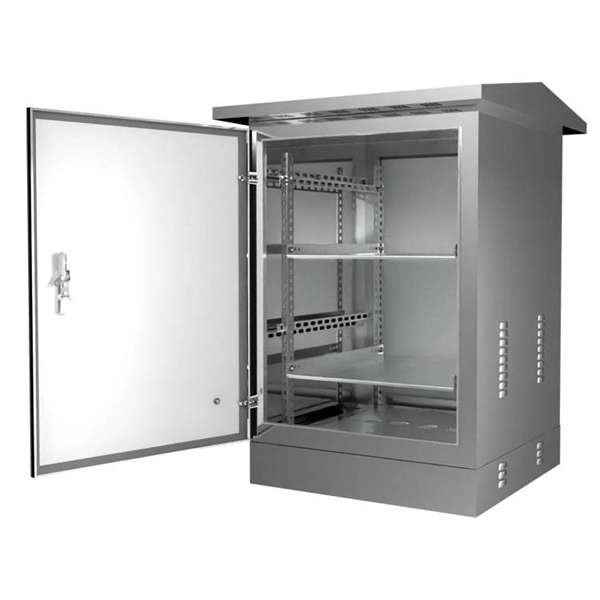
The modern world relies heavily on electrical and communication cables that must be managed and supported across vast distances in commercial and industrial settings. A cable tray is an organized support structure designed to secure and route these insulated electrical cables. In the electrical wiring of buildings, a cable tray system is used to support insulated electrical cables used for power distribution, control, and communication. Cable trays are used as an alternative to open wiring or electrical conduit systems, and are commonly used for cable management in. Whether you're planning a new office setup or upgrading your existing network, the choice of a cable tray system plays a significant role in ensuring the reliability and scalability of your structured cabling solution. It acts as a. en completely installed, without damage either to conductors or structural system use maintain spacing or to keep cables in place when the tray is ect the minimum bend ra-dius for cables as they exit the bottom of the cable tray. A rung spacing of 6 to 9 inches (150 to 230 mm) is preferable when. Explore various cable tray types and sizes for electrical installations. Learn about ladder, perforated, solid-bottom, wire mesh, and channel trays in this complete guide. What is Cable Tray Systems? 1.
[PDF]
Drawing on IEC standards and industry research data, it outlines the coverage of mainstream outdoor fiber optic cable types, selection criteria, and best practices for installation, providing a systematic reference for outdoor fiber optic cable deployment. This document serves as a guide for outdoor fiber optic cable selection and installation for professionals in the telecommunications industry. Fiber optic cables for outdoor applications are engineered to withstand the more demanding conditions seen outside, from environmental extremes to mechanical forces. These are the outdoor fiber optic cables you see strung along telephone poles (aerial), installed inside an underground duct, or even. Outdoor fiber optic cables transport data and communications signals over long distances while enduring extreme environments. Whether you're linking buildings, running broadband in rural areas, or building 5G infrastructure, the right cable matters. It affects performance, maintenance, cost, and reliability. Our team will make sure the configuration is tailored to your needs and will provide a detailed quote. Email us using the Request a Quote below, or. hing, conduit and temp rature variations. The Outside Plant cable. These cables are thoroughly tested designed for installation in pathways that are subjected to wide product line offers 6 and 12 fibers per and verified to Telcordia GR 20 a loose tube cables and hybrid design o ts to specific.
[PDF]
Use this worksheet to input values for all variables that will impact your system's performance. After entering your values, please ensure you click the 'Calculate Link Loss' button at the bottom of the page to generate your total link loss. Add connectors, splices, bends, and safety margin easily. See results instantly above the form, then adjust values. Choose a mode, then enter values and optional losses. All calculations use base-10 logarithms. mW must be greater than zero. Used only in measured attenuation mode. Length is needed. The power budget refers to the amount of fiber optic cable plant loss that a datalink (transmitter to receiver) can tolerate in order to operate properly. Sometimes the power budget has both a minimum and maximum value, which means it needs at least a minimum value of loss so that it does not. To detect whether the link runs properly, the following calculation should be performed. It is often the case to calculate the maximum signal loss across a given fiber link during optical cable installation. First, you should be aware of the fiber loss formula: The Total Link Loss = Cable. Therefore, it is very important to calculate the fiber loss and take appropriate steps. In order to get the most reliable results, an Optical Time Domain Reflectometer (OTDR) trace of the actual fiber connection should be completed. This will provide you with the real.
[PDF]
Fiber testing is the process of verifying the performance of optical fiber cabling. This process includes a range of tests and measurements such as insertion loss, optical return loss, and fiber length. It encompass.
[PDF]
This article discusses the significant specifications of ADSS fiber optic cables, providing information about its structural features, mechanical performance, optical control, and environmental tolerability. In the realm of aerial fiber optic infrastructure—where cables must withstand harsh weather, high voltages, and mechanical stress— ADSS (All Dielectric Self-Supporting) fiber optic cables stand out as a game-changer. Designed specifically for deployment alongside power lines and utility poles, ADSS. AFL-ADSS® (All-Dielectric Self-Supporting) fiber optic cable is a non-metallic cable which supports its own weight without the use of lashing wires or messenger cables. AFL-ADSS® (All-Dielectric Self-Supporting) cable is ideal for installation in distribution as well as transmission environments. American Tech Supply is your reliable source for ADSS (All-Dielectric Self-Supporting Cable), Fiber Cable, Ribbon Cable, Armored, Gel and Gel Free Single-Mode Fiber cables. Both single mode and multimode fibers can be arranged in ADSS cables with a maximum of 144 fibers. They are adopted widely because they are made of fully dielectrics, are relatively lightweight, and can be installed even without conducting.
[PDF]
To help you achieve stable and reliable 800G connections between different brands and models of equipment, we have prepared this concise selection guide. As network speeds escalate to 400G and 800G, proper cabling infrastructure becomes critical for maintaining signal integrity and maximizing performance. Extreme Networks cables provide optimized solutions for high-speed data centers, offering reliable connectivity for next-generation applications. A reliable sourcing strategy must prioritize Multi-Source Agreement (MSA) compliance, rigorous EEPROM compatibility. 800G Ethernet DAC cables, as a direct-connection solution based on high-speed copper cabling, are widely used in short-distance connection scenarios within racks and between adjacent racks. With their simple structure, low power consumption, and convenient deployment, DACs provide a cost-effective. This article provides a comprehensive overview of FS's 800G transceivers and DAC/AOC cables, including product lists, advantages, and application scenarios, offering tailored network solutions for data centers. FS provides a comprehensive portfolio of 800G optical transceivers and DAC/AOC cables. At 400G, interconnect selection was a two-step process: measure the distance, pick copper or fiber. Passive copper comfortably reached 3–5 meters. Multimode fiber handled everything from the rack to the end of the row. 800G changed the underlying physics.
[PDF]