This report provides a comprehensive analysis of the optical active device market, encompassing various segmentations: By Type: Lasers, modulators, photodetectors, amplifiers, etc., each with their own specific performance characteristics and applications. The global Active Optical Devices market was valued at US$ million in 2023 and is anticipated to reach US$ million by 2030, witnessing a CAGR of % during the forecast period 2024-2030. The Global Info Research report includes an overview of the. Optical Active Device by Application (IT Industry, Telecom, Other), by Types (Optical Transceiver Module, Light Detector, Light Modulator, Other), by North America (United States, Canada, Mexico), by South America (Brazil, Argentina, Rest of South America), by Europe (United Kingdom, Germany. The Optical Active Device Market Size was valued at 36. 3 USD Billion in 2024. The Optical Active Device Market is expected to grow from 38. North American market for Active Optical Devices is estimated to increase from $ million in 2024. Abstract—A wireline receiver consisting of a linear equalizer, a decision-feedback equalizer (DFE), a clock and data recov-ery (CDR) circuit, and a demultiplexer (DMUX) employs new circuit and architecture techniques that afford substantial power savings. Realized in 28-nm technology, the 56-Gb/s.
[PDF]
Polarization dependent loss (PDL) is a measure of the peak-to-peak difference in transmission of an optical component or system across all possible states of polarization. It is the ratio of the maximum and minimum transmission of an optical device with respect to all polarization. The determination of polarization dependent loss has become a stan-dard measurement when character-izing passive optical components. In optical networks, where polarization is not constrained and changes randomly, the PDL of components can accumulate in an uncontrolled manner. This effect can. arch, and 3) Matrix measurements using Mueller or Jones matrices. Each method has its own advantages and disadvantages in terms of measuremen ice under test (DUT) while the DUT's output power is monitored. The built-in motor con-trolled PDLE units have low insertion loss, low backreflection, low PMD and flat wavelength response. This. This is the authors' extended version of an article that has been published in Proc. 21th ITG-Symposium on Photonic Networks, ISBN 978-3-8007-5424-3. The final version of record is available at https://www. de/buecher/455423/itg-fb-294-photonische-netze. Abstract—A number. Abstract—State-of-the-art polarimeter calibration is reviewed. Producing many quasi-random polarization states and moving/bending a fiber without changing power allows finding a polarimeter calibration where the degree-of-polarization reaches unity and parasitic polarization-dependent loss is.
[PDF]
Learn how to extend GDB with optical signal breakpoints for efficient photonics chip debugging and testing with practical implementation steps. Debugging photonics chips requires specialized tools that can monitor and analyze optical signals alongside electronic ones. Legal status (The legal status is an assumption and is not a legal conclusion. Google has not performed a legal analysis and makes no representation as to the accuracy of the status listed. ) Current Assignee (The listed assignees may be inaccurate. These modules leverage advanced signal processing, modulation, and high-speed interfaces to provide high bandwidth, low latency, and reliable performance. Standard debugging tools like. modules used with NADDOD switches, for reference by technicians and users. For any questions, please contact NADDOD. When testing PRBS, there are 3 test nodes: MAC ----> PHY. In view of this, the embodiments of the present invention expect to provide an optical module commissioning device, commissioning method, and electronic equipment to solve the time-consuming technical problem of manually commissioning a DSFP optical module through a commissioning device in. Optical detection chips serve as essential components in intelligent optical computing systems, demonstrating crucial significance. These chips exhibit high sensitivity and broad wavelength response ranges, enabling precise optical signal reception and conversion while providing reliable data input.
[PDF]
Calibration & Repair services in Ireland. 5 day turn around with competitive pricing! View full electrical test and measurement equipment list here. is an independent calibration laboratory focused on meeting the total quality requirements of industry. Proper calibration of today's sophisticated test and measurement equipment is essential for preserving measurement accuracy, complying with international standards. Parameters covered include; Temperature, Humidity, Dewpoint, Various Gases, Pressure, Electrical, Weights & Scales, Analytical and some Specialist calibrations. Calibration is performed using the very latest Calibration Equipment/Standards & Calibration/Asset Management Software. Fast Efficient. PTM Calibration offers a wide range of services that complement our core business. We aim to be your one stop shop for all your calibration, test & measurement needs. From major blue chip companies & medium enterprises to small companies and sole traders. Including: aerospace, pharmaceuticals. OptiCal Sciences are an authorised service centre with service, repair and calibration experience and procedures for an extensive variety of models from a wide range of manufacturers.
[PDF]
XGS-PON is a 10 Gbps symmetric passive optical network (X=10, S=symmetric). Optical fiber's greater transmission capacity and speed deliver upstream and downstream (symmetric) speeds of up to 10 Gbit/s (gigabits per second) on the road to connecting users in the last. 10G-PON (also known as XG-PON or G. 987) is a 2010 computer networking standard for data links, capable of delivering shared Internet access rates up to 10 Gbit/s (gigabits per second) over optical fibre. This is the ITU-T 's next-generation standard following on from GPON or gigabit-capable PON. It is commonly used to implement the link to the customer (the last kilometre, or last mile) of fibre-to-the-premises (FTTP) services, using a. Short on Ethernet ports and looking to connect an extra device or two to your wired network setup? You're likely to encounter two options: an Ethernet splitter, and an Ethernet switch. Here's why you should choose the switch every time. What Is an Ethernet Splitter? An Ethernet splitter is a simple. Recommendation ITU-T G. 1 describes a flexible optical fibre access network capable of supporting the bandwidth requirements of business and residential services and covers systems with nominal line rates of 2. 4 Gbit/s in the downstream direction and 1. 984 G-PON and ITU-T G. 9807 XGS-PON wavelengths to coexist within the same single mode fiber cabling and across the same passive optical distribution splitters. This means that users can.
[PDF]
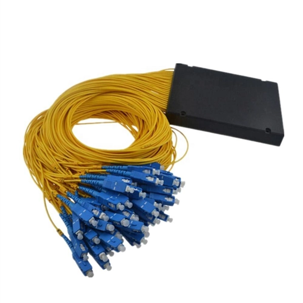
Total number of cores = Number of branches × Number of cores per branch If there are no branches, the number of branches equals one. For example, an MTP®-8 trunk cable with four branches and eight cores per branch has a total of 32 cores (4 × 8 = 32). For example, if you have three optical fiber access switches, you need to have three cores. (actually use a four core optical cable) This is because apart from one-core optical fiber, there are basically no optical cables with an odd number of cores, such as three-core, five-core, etc. It is worth. Fiber cores are the heart of fiber optic cables, transmitting light signals that carry data. Made from either high-quality glass or plastic, the core plays a critical role in determining the cable's performance. The total number of cores for a 1pc fiber patch cable is calculated as the number of. One key factor is the number of cores, which impacts how much data you can transmit. Single-mode: A. Common fiber cores include 1 core, 2 cores, 6 cores, 8 cores, etc., and there are many types. This article will focus on the number of fiber cores, introducing their respective characteristics and usage scenarios. Of course, this is a general situation, and it can be considered as follows: 1.
[PDF]
Abstract: Detecting partial discharges in cable joints is critical for timely defect identification and reliable transmission system operation. The electric field distribution of the optical fiber-implanted cable joint was simulated, followed by electrical performance tests, demonstrating that optical fiber implantation had a negligible effect on the electrical properties of the cable joint. A platform utilizing Mach–Zehnder–Sagnac. The results show that the average sensitivity of the sensor in the 10 kHz–80 kHz range is 71. 0 dB higher than that of the piezoelectric transducer, with a maximum signal-to-noise ratio of 65. To improve the long-term reliability and sensitivity of the sensing system, a novel method for cable joint monitoring based on implanting optical fibers. However, there is an industry gap in the literature about the highly sensitive fiber optic-based PD solution based on the acoustic emission principle. This paper aims to fill such an industry gap. In this paper, the fiber optic-based PD sensing (OptiFender) technology is applied to monitor the PD.
[PDF]
This step-by-step guide aims to provide a comprehensive understanding of the techniques and considerations involved in successfully connecting optical fibers, offering invaluable insights for professionals and enthusiasts in the field. In high-speed data networks, the seamless integration of fiber optic cables with SFP (Small Form-Factor Pluggable) modules is critical for reliable signal transmission. SFP transceivers bridge electrical and optical signals, making them indispensable in data centers, telecom networks, and. Proper connection of fiber optic cables is essential to harness these benefits fully, as even minor errors can lead to significant performance issues like signal loss. This article will guide you through the necessary tools, materials, and methods on how to connect fiber optic cables effectively. This section describes how to install optical transceivers on the SFP or SFP+ ports and connect them to the ports of the peer device using optical fibers according to the network plan. The USG supports both 1 Gbit/s, 10 Gbit/s, and 40 Gbit/s optical modules. The optical modules at both ends are. There are many types of fiber optic connectors, including SC, LC, FC, ST, D4, MU, MT/MPO, etc. These connectors can be divided into single-mode and multi-mode fiber optic connectors according to their structure and purpose. In this tutorial.
[PDF]
Lasers, modulators, and photodiodes form the core architecture of optical transceivers, enabling light-speed communication across global networks. Lasers generate the optical carrier. Modulators encode digital information. An optical transmitter is a crucial device used in fiber optic communication systems. Its primary function is to convert electrical signals into optical signals It involves modulating electronic system data and transforming it into light pulses using a laser or LED, and sending the pulses through. The optical transmitter and the optical receiver are the core components that enable this process, forming the electronic-to-optical and optical-to-electronic gateways necessary for modern, high-capacity data transmission. It takes data from an electronic system, uses a laser or LED to modulate that data into pulses of light, and then sends those pulses down the fiber. Together, lasers, modulators, and. At the core of a fiber optic system is the optical fiber – a flexible, transparent strand of glass, thinner than a human hair. Optical fiber is formed by drawing glass or plastic to a diameter slightly thicker than that of a. What are the main elements of an optical transmitter? Data decoder/demodulator, electrical interface, detector, optical interface.
[PDF]
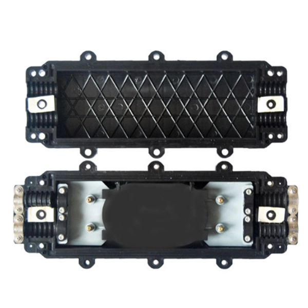
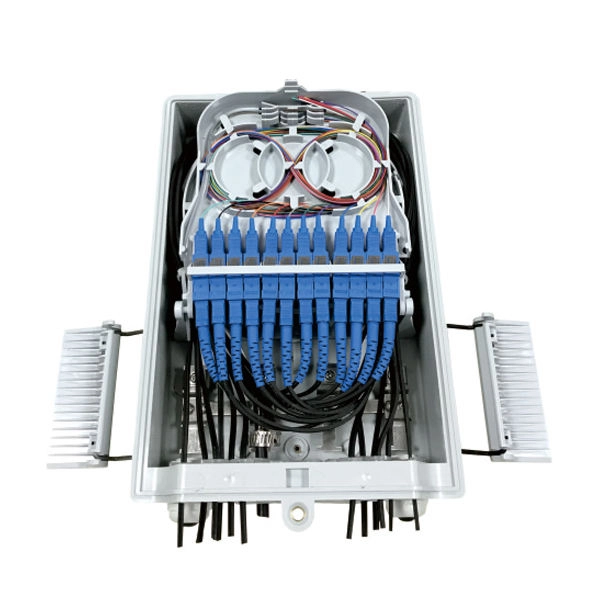
OPGW cable joint box installation involves several key stages: selecting the appropriate location, preparing both the cable and the joint box, splicing fibers, and sealing the joint box properly. Adhering to these steps ensures optimal performance and longevity of the telecommunications system. Optical fiber junction boxes are essential components in outdoor optical fiber cable installations. In this article, we will discuss the necessary steps and best practices. The Indoor/Outdoor Splice Box is a wall-mounted, indoor/outdoor fiber splice enclosure for centralized splice-only applications. These boxes are well suited as optical cable splice collection points for MDU (Multi-Dwelling Unit) residential fiber network applications, MTU (Multi-Tenant Unit). The installation of an optical cable junction box is crucial in ensuring the integrity and performance of optical networks. As we enter 2024, adhering to best practices not only enhances system reliability but also mitigates potential issues that can affect customer experiences. Installing a fiber optic splice closure efficiently and effectively requires attention to detail and. AFL's SB01 splice enclosure provides protection from all types of elements. From weather to bullets, the iron and steel construction requires no additional protective covering. Furnished with four plugged cable ports (2 aluminum and 2 plastic) for either All-Dielectric Self-Supporting (ADSS) or.
[PDF]
FS provides Optical Line Terminals, free & fast delivery, expert tech support, outstanding warranties. Cisco's NCS1K-OLT-C NCS 1010 Optical Line Terminal offers advanced C-band transmission for optical networks. With superior performance and reliability, it suits large-scale enterprise infrastructures and service providers. Explore our range of high-quality GPON, EPON, and XG (S)PON OLT products. However, in the context of surveying and distance measurement, "Price Optical Line Terminals" likely refers to precision optical instruments used for accurate distance and positional measurements. These advanced tools integrate optics, electronics, and signal processing to deliver reliable data in. High-Performance 16-Port XGS-PON OLT with 40G/100G Uplink CapabilityPLANET XGPL-16000 is a high-density 16-Port XGS-PON Optical Line Terminal ( OLT) designed for next-generation fiber broadband access. 2065 olt ftth optical line terminal products are offered for sale by suppliers on Alibaba. com, of which fiber optic equipment accounts for 85%.
[PDF]
The Italy optical fiber cable market is poised for significant transformation from 2026 through 2033, driven by a confluence of technological evolution, economic shifts, and evolving regulatory frameworks. is a leading company in the design and production of fiber optic cables, offering a comprehensive range for various applications. With a strong commitment to quality and innovation, Cavicel has established a global presence, ensuring their high-quality optical cables are recognized. Tratos is an international cable manufacturer with hundreds of thousands of square meters of facilities in Italy, the UK, Germany, and Spain. The company manufactures all the components of its cables, including conductors, insulating compounds, fiber optics, and finished cables. The production site. An innovative research center that brings together the entire Italian fiber optic communication network, where new technological solutions can be tested and developed, from fiber sensing to digital twin. As digital infrastructure investments accelerate across Europe, Italy's import-export.
[PDF]
An optical module is a typically hot-pluggable optical transceiver used in high-bandwidth data communications applications. Optical modules typically have an electrical interface on the side that connects to the inside of the system and an optical interface on the side that connects to the outside world through a fiber optic cable. The form factor and electrical interface are often specified by an int. Electrical Interface TypesThere have been multiple variants of the electrical interface of optical modules that have been used over the years. The earliest forms of optical modules had an analog electrical interface. In the transmit dir. Many different forms of optical modulation and multiplexing have been employed in optical modules. The most common modulation technique historically has been or NRZ.
[PDF]
SFP28 (Small Form-Factor Pluggable 28) is an enhanced version of SFP+, designed to support 25Gb/s data rate transmission while maintaining the same package type. SFP28 is backward compatible with SFP+. However, compatibility can vary based on the specific SFP models, networking equipment, and vendors involved. It's advisable to consult your vendor for precise information regarding compatibility. ①. This article helps network engineers and field techs confirm SFP backward compatibility when mixing SFP, SFP+, and SFP28 optics in the same switching ecosystem. You will get concrete specs, a decision checklist, and troubleshooting patterns that show up in daily operations. ① Plug a 1000BASE-SX SFP transceiver into the SFP port on a gigabit. Common form factors are SFP (1 G), SFP+ (10 G), SFP28 (25 G), QSFP+ (40 G) and QSFP28 (100 G). The question we answer below is simple: “Which of these can I mix and match without killing the link? What “compatibility” really means? All reputable transceivers follow the Multi-Source Agreement (MSA). SFP28 optical transceiver modules provide a transmission rate of 25 Gbps and use LC connectors. 25G SR/eSR are not supported for use. Q: Can I use an SFP transceiver in SFP28 ports? A: Yes, you can. However, it's important to note that while SFP transceivers and cables can be plugged into SFP28 ports, they won't support the higher 25Gb/s data rate of the SFP28.
[PDF]
The SFP optical module is a standardized, modular assembly designed to be quickly installed or removed from a device's port without requiring the device to be powered down. This key feature—being hot-pluggable —is essential for simplifying network maintenance and minimizing downtime. SFP (Small Form-factor Pluggable) is a compact, hot-pluggable network interface module used to connect network devices (switches, routers, firewalls) to fiber optic or copper cables. It converts electrical signals into optical (or copper) signals and vice versa. An SFP transceiver acts as a compact, hot-swappable optical transceiver that. An SFP switch uses Small Form-Factor Pluggable (SFP) modules to form a network switch for high-speed connectivity between devices. These interchangeable modules support various media types, including copper or fiber-optic cables, providing flexible networking options based on specific requirements.
[PDF]