Welcome to our light sources category, where we offer advanced calibration solutions designed for precision and accuracy in scientific measurements. Our selection encompasses two primary subcategories: “Wavelength Calibration” and “Radiometric Calibration,” featuring state-of-the-art products. This. As a result of a 2-year research project, finalised in 2020, GL Optic developed new calibration facilities and created Calibration and Research Laboratory of Optical Radiation ( CARLO ). Today, CARLO is the only laboratory in Central and Eastern Europe equipped with the Black Body Radiator – the. We offer two types of light sources for calibration: Pen-Ray line sources for the wavelength calibration of spectroscopic instruments and calibrated irradiance sources covering UV-NIR. All Avantes spectrometers are factory wavelength calibrated and do not require recalibration as they have fixed slits and optics. Options include mercury-argon (253-1700 nm), krypton (427-893 nm), neon (540-754 nm), argon (696-1704 nm) and xenon (916-1984 nm) gas-discharge emission sources. Multiple LED sources can be efficiently combined into a single output beam, and offer major advantages such as long life-time, easily tunable spectrum, high power stability, and ultra-fast switching (on the microseconds level) without using moving mechanical components. Multi-Wavelength Collimated.
[PDF]
When the LOS light turns red or blinks red, it usually means your ONT or fiber router is not receiving the optical signal properly from the network. In most cases, this is not just a normal WiFi issue. It usually points to a signal-side or line-side problem rather than a small. The LOS light on your router indicates the status of your internet connection to the Internet Service Provider (ISP). When it's green and steady, everything is fine. Fortunately, diagnosing and resolving these issues doesn't have to be complicated. In this comprehensive guide, we will walk you. Whether your modem is blinking orange, your router has a solid red light, or you are staring at a mysterious "DS" indicator, you will find the answer below. A solid green or white light on your modem or router almost always means everything is working normally. You might feel like you're staring into the abyss of digital darkness, wondering what went wrong. Before you panic or call tech support, there are several simple fixes you can try at home that often solve this problem in minutes. Existing Krishii Fiber customers can share their registered mobile number, area and a.
[PDF]
It enables uniform, shadow-free lighting by directing light along the same optical axis as the lens. When integrated into specialised lenses, the beam splitter divides the incoming light into two paths: one beam illuminates the object, while the other is used for image capture. Beamsplitters are fundamental components in optical engineering, serving to precisely divide a single input beam of light into two distinct output beams. This division allows for the simultaneous analysis or utilization of the light's properties along two separate paths. Additionally, beamsplitters can be used in reverse to combine two different beams into a single one. In practice, the reflective layer absorbs some light. It is a crucial part of many optical experimental and measurement systems. A cube beam splitter is, at its essence, an optical device that splits an incoming light beam into two sections. What are beamsplitters and how are they used in optics and photonics applications ? Beamsplitters are optical components that are used to. The beam splitter splits and then recombines infrared radiation, while the detector picks up the resulting signal. It's sensitive to both intensity and frequency. Together, they decide just how accurately an instrument captures those unique infrared “fingerprints” from different substances.
[PDF]
In fiber-optic communications, wavelength-division multiplexing (WDM) is a technology which multiplexes a number of optical carrier signals onto a single optical fiber by using different wavelengths (i.e., colors) of laser light. This technique enables bidirectional communications over a single strand of fiber (also called wavelength-division duplexing) as well as multiplication of capacity. The. SystemsA WDM system uses a at the to join the several signals together and a at the to split them apart. With the right type of fiber, it is possible to have a device that does both s. Originally, the term coarse wavelength-division multiplexing (CWDM) was fairly generic and described a number of different channel configurations. In general, the choice of channel spacings and frequency in these co.
[PDF]
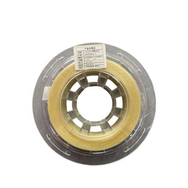
Light decay in light divisions refers to the decrease in light intensity as it travels through optical fibers or other transmission media. This decay can occur due to a number of factors, including absorption, scattering, and reflection. If you don't know what kind of losses to expect in your system, you won't know how many other components. It is also known as fiber loss or signal loss. The signal attenuation of fiber determines the maximum distance between transmitter and receiver. Another important property of optical fiber is. Fiber loss, also called fiber optic attenuation or attenuation loss, refers to the loss of signal between input and output. Losses can be introduced by various means such as intrinsic material absorption, scattering, bending, connector loss and more. This loss can significantly reduce the effectiveness of optical fibers in applications such as telecommunications, imaging systems, and even simple fiber-optic tools like flashlights. In the early days of.
[PDF]
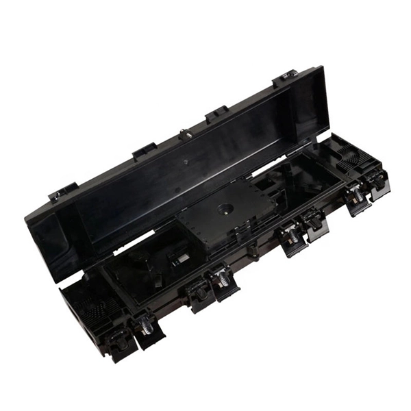
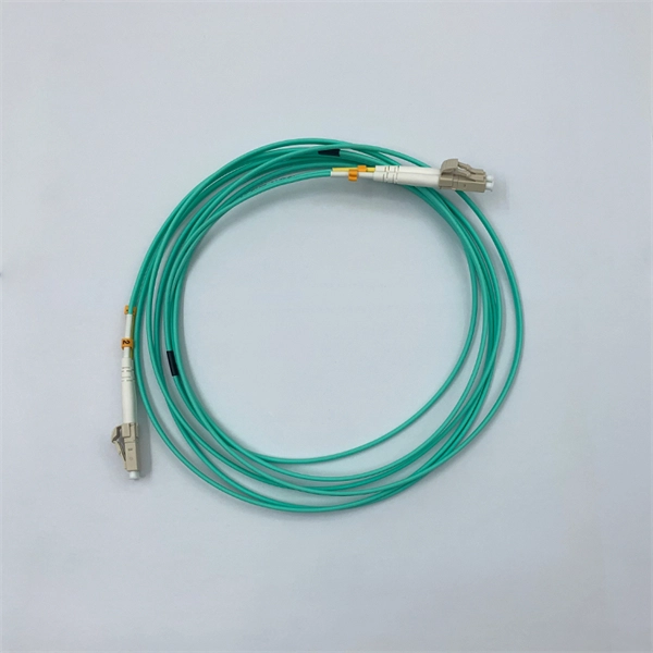
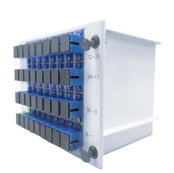
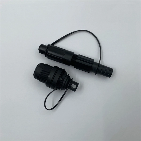
Through the adapter in the distribution box, the optical signal is led out by the optical jumper to realize the optical wiring function. An optical cable consists of three primary parts: the core, the cladding, and the protective sheath. The core is at the center of the optical cable and serves as the pathway for transmitting light signals. Surrounding the core is the cladding, which has a lower refractive index than the core. In the complex architecture of fiber optic networks, the Optical Distribution Frame (ODF) serves as the linchpin for organizing, protecting, and distributing optical signals. Whether in data centers, telecom central offices, or enterprise network rooms, ODFs enable efficient fiber management. The optical fiber distribution box is to protect the connection point where the optical cable is connected to the user end, so that the optical cable access point is stable, dustproof and waterproof. What is a fiber distribution box? 2. The. A fiber distribution box (FDB) functions as a central hub in fiber optic networks where the main cable is split into multiple individual fibers for distribution to end users. These boxes protect sensitive fiber connections from environmental factors while providing an organized framework for.
[PDF]
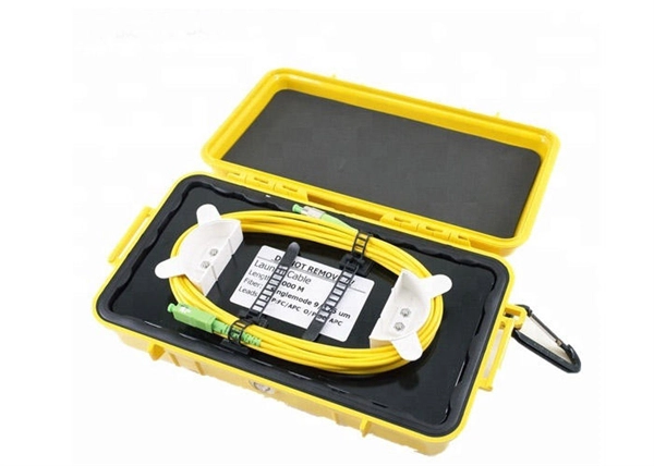
The worker must then connect one end of the fiber optic cable to a light source. Then, once they have done this they will turn on the light source and press the button on the. When it comes to testing fiber optic cables, a Visual Fault Locator (VFL) is an essential tool in your toolkit. A VFL is used to detect faults, breaks, or bends in fiber optic cables by emitting a bright red light that is visible even through the fiber's jacket. It's a cost-effective and. How to use fiber optic red light pen? It can be seen from the above that the red light pen has many uses, but its most common use is to detect the connectivity of the optical fiber and locate the fault point of the optical fiber. more How to use a VFL to identify a fiber optic cable from end to end. Viavi VFL:https://amzn. to/3L7cL6RTools I use:3 Hole Strippershttps://amzn. Within the pen, a small but powerful laser sends out an intense red light. Here is how the pen helps detect errors. If the fiber optic cable is appropriately intact and. The RPEN-210 is a necessity tool that should not be missing from any fiber plant manager or fiber optic installing technician. The Visual Fault Locator (VFL) Pen has a visible red light source centered on 650nm. Tool sends visible light over a fiber strand with a 10mW power, good enough to reach.
[PDF]
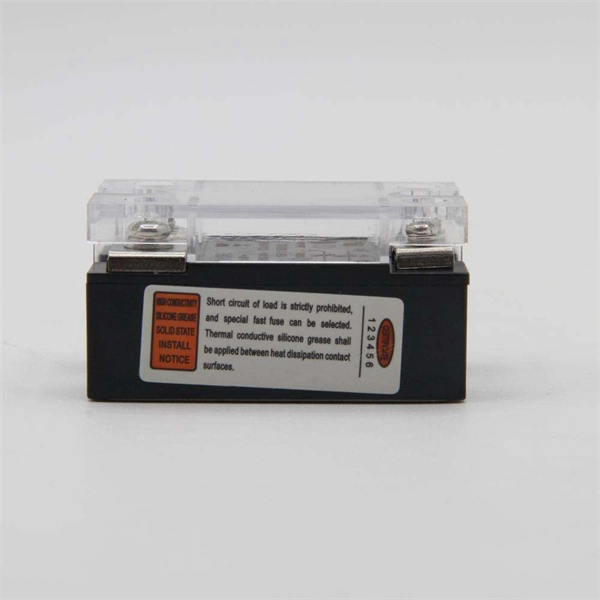
Check the electrical load and ensure that the sensors do not exceed the 10 Amp maximum. Check each wire for damage that may lead to a short. Check the following: Check if all cable connections are tightened with a torque moment of 14Nm (17Nm for the M10 model). Check if the surface area. Channel has NO voltage and there is an active fault. Check for tripped or missing circuit breaker Sticky fault on the channel. Sticky Fault - an indicator that a fault has occurred that will stay until the indicator has been cleared manually. Channel has NO. Each powernet distribution box (PNDB) on the vehicle provides up to 4 low amperage circuits (30 amp and less), and up to three high amperage circuits through midi fuses. The fuses are located behind a cover on the face of the PNDB. On vehicles equipped with a cab load disconnect switch (CLDS), the. I have the following issues, green light on shunt all red lights on distributor, no SOC on screen. Everything else is working great. In troubleshooting I removed all the fuses from the distributor just to see if the fuse lights would not illuminate red and get green power. Any. Show the control box indicator lights. Show the accessory response (or lack of response). For LED Light Kit issues, also provide a photo of the LED Y-cable (to confirm which version you have). Videos and photos are required to file warranty claims with the manufacturer.
[PDF]
This comprehensive guide will equip you with the knowledge and steps needed to safely test a lighting circuit using a multimeter. We will cover the essential safety precautions, different testing methods, interpreting the results, and troubleshooting common issues. Understanding the principles. Multimeters are versatile tools used by electricians and hobbyists alike to diagnose electrical problems and ensure the proper function of electrical devices. We'll explain how to measure AC and DC voltage, test for continuity, measure capacitance, measure frequency, and test diodes. Hence the 'multi'-'meter' (multiple measurement) name. The most basic things we measure are voltage. Here is a step-by-step guide on how to test a light fixture with a multimeter for beginners: Step 1: Turn Off the Power Before you begin testing the light fixture, it is crucial to turn off the power to the fixture at the circuit breaker. It's an indispensable tool for troubleshooting and maintaining electrical circuits. Different types of multimeters offer varying degrees of precision and. An easy way to test a light fixture is to remove the bulb and replace it with one that you know is working. If you don't happen to have a working bulb handy, you can use a light socket tester or test the fixture with a multimeter.
[PDF]
Los sensores de luz presentan una variedad de dimensiones, desde modelos compactos ideales para aplicaciones domésticas hasta sensores más grandes diseñados para entornos industriales. Estas dim.
[PDF]