Check the steps ① whether the user network card is disabled, ② check whether the network cable is normal with a network cable tester, ③ replace the optical modem LAN port or other ports of the router and switch to test whether normal. Fiber optic networks are celebrated for their speed and reliability, but even the best systems can encounter problems. When issues like signal loss, slow speeds, or intermittent connectivity arise, systematic troubleshooting is key. This guide will walk you through diagnosing and resolving common. We have a fibre run, SM, 650 meters, with Level1 dumb switches at each end, I get Link lights at both ends, but there's no network traffic. Switch A is on the router end, devices connected to this switch get DHCP leases and can browse the internet without issue. These high-speed, high-capacity communication networks are increasingly replacing copper cables, offering superior performance and. However, even the most advanced fiber-optic networks can encounter issues that disrupt performance. This comprehensive guide delves into the most common FTTH problems faced by users, providing detailed troubleshooting steps and real-world solutions. Whether you're a network engineer, IT manager, or service provider, understanding these challenges and how to address them is critical for maintaining high-performance, reliable.
[PDF]
This diagram highlights media converters, switches, and cable types. Also thanks to Init7 (for the great service), r/FiberOptics and FS for providing me with what I needed to get this setup going. If you find this article useful and you are considering Init7 as your provider you can use my referral code “20700408098” to get CHF 111. - off hardware and also support me. Keeping this page as a placeholder for now. Have any questions? Talk with us directly using LiveChat. A fiber optics network diagram illustrates how high-speed data travels from an internet service provider to end users. By using light signals, fiber optics provide faster speeds and better reliability than. MS Visio has long been the default choice for drafting fiber network diagrams, and with the right stencil libraries it can be used to draw everything from backbone routes to detailed patch panel layouts. When fiber techs look for visio fiber stencils, they are usually solving a very practical. Be among the first to receive important product updates, insights and news. Fiber optic cable is used for everything from demarcation point wiring to network signal distribution to video signal extension. Often, fiber enters the structure to a centralized rack or data room where it is connected to a modem. The modem connects to a network switch which connects each remote.
[PDF]
In this guide, we will walk you through the process of setting up a network switch, from selecting the right equipment to connecting and testing the network. Ethernet switches, also called network switches, connect multiple devices via Ethernet cables. In contrast, a router connects your local area network (LAN) to the internet's. A practical, current guide to planning, pulling and terminating Cat6/Cat6A cable — tools, techniques, testing and labeling for reliable results. By Thomas McCormack • Updated Mar 17, 2026 • 12 min read • Lead Technician and Engineer, Data Wire Solutions Disclosure: Some links may be affiliate. With an Ethernet cable, you can hardwire your devices to your network, providing fast and efficient. Your ethernet switch doesn't come with any ethernet cables, so you want to have some on hand when setting up your switch. You'll need one cable to connect your ethernet switch and router together (assuming you want to provide your devices with an ethernet connection to the internet), and an. A network switch is a crucial component in any modern network, enabling seamless communication between devices. By the end of this tutorial. Connecting a network switch involves physically connecting devices using Ethernet cables and configuring them as needed, ultimately expanding your network connectivity and improving network performance. Connecting a network switch is a foundational skill for anyone managing a home or small business.
[PDF]
For each laptop, PC, or game console in the setup, you shall connect both their video out and USB port to the KVM switch. For each system, the ports are grouped and numbered. Put each cable in the rig.
[PDF]
Most modern fiber-enabled network switches require an SFP transceiver module featuring a duplex (two strand) multimode OM3 or duplex single mode OS2 connection with LC connectors. Direct attach cables with pre-terminated SFP connections may also be used. Download the. In this article, we'll explain how to connect multiple Ethernet switches using fiber optic cables and the equipment required for this to work. Network topology refers to the way in which the links and nodes of a network are arranged in relation to each other. Download the Application PDF SFP transceiver. Choose an SFP module based on the fiber optic cabling that will be connected to the network switches. Always integrate duplex (two strand) fiber optic cabling or higher strand counts. So all PCs connected to each switch would reach the LAN/WAN from the other switch. The connection between two or more Ethernet switches in a certain way (Uplink port, etc. ) is called the cascade. Connecting a fiber optic switch involves several steps, ensuring compatibility between the switch's ports and the fiber optic cable. The process requires understanding the type of fiber optic port on your switch and selecting the appropriate transceiver module. Fiber optic switches utilize.
[PDF]
Most modern fiber-enabled network switches require an SFP transceiver module featuring a duplex (two strand) multimode OM3 or duplex single mode OS2 connection with LC connectors. Direct attach cables with pre-terminated SFP connections may also be used. Download the Application. CONFIGURING THE SWITCH IN DESIGO CC/CERBERUS DMS. CYBERSECURITY DISCLAIMER. 44. This tutorial will explain the steps required to configure fiber optics on a Cisco switch and ensure proper connectivity in your network. This chapter includes the following sections: •Information About Fibre Channel Interfaces, page 1-1 •Configuring Fibre Channel Interfaces, page 1-8 •Configuring Global Attributes for. : 192. 0 De livery of solutions fulfilling the Customers' multitude o. This document is intended to serve as a guide for architecting and deploying fiber optic networks in a customer environment. This installation planning guide describes some basic fundamentals of fiber optic technology, considerations for deployment, and basic testing and troubleshooting procedures. Fiber optic cabling is increasingly used to connect network switches and other datacom equipment, especially in long-distance and mission-critical applications. Fiber provides: Increased internet signal bandwidth.
[PDF]
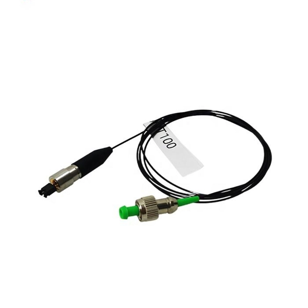
Optical transceivers are crucial components for network switches, enabling them to connect to fiber optic networks and transfer data at high speeds. The common use is to convert the electrical signal in the twisted pair into an optical signal. It is generally used in Ethernet copper cables that cannot be covered and optical fibers must be used to extend the transmission. Optical transceiver is a very cost effective and flexible device that is commonly used to convert electrical signals in twisted pair cables to optical signals. An SFP transceiver integrates both transmitting and receiving functions into a compact, standardized module, enabling seamless conversion between electrical and optical signals. Its flexibility supports a broad range of applications—from short-reach enterprise connections to long-haul single-mode. SFP (Small Form-factor Pluggable) is a compact, hot-pluggable network interface module used to connect network devices (switches, routers, firewalls) to fiber optic or copper cables.
[PDF]
Run the display cpu-usage command to view the CPU usage. A switch is considered running normally if its long-term average CPU usage does not exceed 80% and its highest temporary CPU usage does not exceed. Method 1: Run the display cpu-usage command to check the CPU usage. The System CPU. Huawei Switches: CPU Utilization This check monitors the CPU utilization on Huawei switches. It supports the stacking function in which multiple devices are connected together to logically function as one device. Default levels are set to 80, 90 percent. These levels can be configured in WATO. The. In the following table, we tried to collect the most common OID switches from different manufacturers (Cisco, Dlink, Huawei, HP, etc. ) that you may want to monitor (traffic, processor temperature, processor load, fan speed, voltage, load, state of links and pairs, free memory, etc. This is the. The following uses the Moduletek SFP-10G-LR module connected to a Huawei S6700 switch as an example to introduce how to read information of the connected optical module on a Huawei switch. Figure 1 Schematic Diagram of Optical Module Connected to Switch 1.
[PDF]
When selecting an SFP module, consider the following factors: Ensure the module matches the speed of your switch or router port (e. Depending on your deployment, choose 850nm, 1310nm, 1550nm, or even CWDM/DWDM wavelengths. SFP (Small Form-factor Pluggable) is a compact, hot-pluggable network interface module used to connect network devices (switches, routers, firewalls) to fiber optic or copper cables. Think of it as the “translator” for your network equipment, converting electrical signals into optical signals. SFP optical modules are the unsung heroes of fiber networking—the essential interface that converts electrical signals from network equipment into optical signals for transmission over fiber optic cable, and vice-versa. Choosing the wrong SFP optical module can result in link failure, instability. Optical transceivers are at the heart of modern fiber networks - connecting switches, routers, and servers with blazing-fast links. Cisco's SFP, SFP+, and XFP modules are among the most widely used standards across enterprise and carrier environments. They determine data rate, transmission. With our expert guide, you can easily maximize network performance while optimizing your expenses the next time you're choosing a switch/router, optic, or supporting cabling. It converts electrical signals into optical (or copper) signals and vice versa. It allows network administrators to adapt hardware to different media types and.
[PDF]
Insert a compatible SFP transceiver into the converter's port, making sure it matches the network's media type and speed. Then, connect one end of the fiber cable to the transceiver and the other to the appropriate port on a switch, router, or another media converter. Fiber media converters translate copper's electrical signals into fiber's optical signals, and back again. This allows networks to extend beyond the 100 m copper limit while gaining higher bandwidth and resistance to electromagnetic interference. In the illustrated setup, each LAN links to a. A fiber media converter is a networking device that allows you to convert a signal from one medium to another. This allows you to connect devices that use different types of cabling, such as a computer. While fiber optic ports are becoming increasingly common on networked electronics, the majority of connected devices still rely on RJ45 twisted pair connections. To help bridge the copper-fiber divide, media converters and transceiver modules (also known as SFPs or mini-GBICs) are often required. Use Fiber Media Converter in Your Network Media converters today are widely deployed in all. It is a device used to convert fiber optic cables to Ethernet cables to provide better connectivity. It is necessary to convert fiber optic signals to Ethernet signals because many network devices can only communicate with Ethernet signals. Fiber optic cables are known for the unmatched speed.
[PDF]
Connect the fiber optic cable: Attach the fiber optic cable's connector to the transceiver module on the switch. Make sure the connector type (e., SC, LC) matches the transceiver module. Fiber optic cabling is increasingly used to connect network switches and other datacom equipment, especially in long-distance and mission-critical applications. Fiber provides: Increased internet signal bandwidth. Most modern fiber-enabled network switches require an SFP transceiver module. A newly added feature on some Microchip Gigabit Ethernet switches is a serial Gigabit media independent interface (SGMII) for one of the ports. This is a low pin count interface for connecting the switch to a Gigabit Ethernet PHY, to a fiber optic transceiver, or to another switch. The following. This document describes how to troubleshoot fiber optic interfaces by addressing some of the fiber optic module and cabling specifications. There are no specific requirements for this document. The information in this document is based on all Catalyst 9000 Series switches. This includes Doppler. Multimode fiber optic switches have emerged as a crucial component, enabling seamless connectivity and efficient data transmission. This is a cost-effective and high performance way to connect network switches. Advantages Determine the length of the fiber run and choose either multi mode for runs under 1000 feet or single mode for runs over 1000 feet. Fiber optic switches utilize.
[PDF]
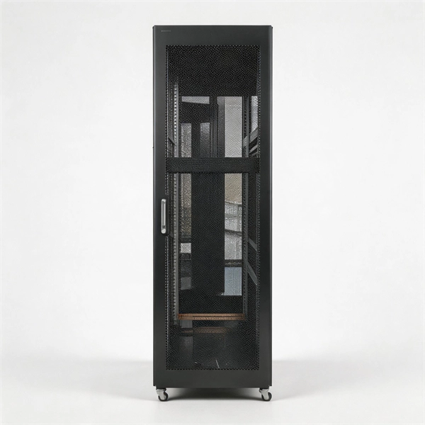
It is a networking tool called an aggregation switch that enables the consolidation of several network connections into a single link. This makes it possible to boost bandwidth and improve network efficiency. What Is an Aggregation Switch? An aggregation switch is a network device that consolidates traffic from multiple access switches, wireless access points, or other edge devices and forwards it. An Aggregation or "Top-of-Rack" switch is designed to connect everything in a rack at high speeds, then have an even bigger pipe out to the rest of the network. The Pro Aggregation does this with it's SFP28 25Gbps ports. The regular Aggregation switch is best used to connect all devices in a rack. Learn about aggregated Ethernet interfaces, LACP, and LAG. 3ad link aggregation enables you to group Ethernet interfaces to form a single link layer interface, also known as a link aggregation group (LAG) or bundle. Amounts or summary statistics are used in place of atomic data rows, which are often collected from several sources when data is aggregated. In place of groups of observed aggregates, summary. Function: Connection point for all devices on a segment of segment of a network that breaks down and absorbs the data flow between all of the connected devices rather than flooding it to all connected devices. Sophisticated routing options. Fault Tolerance and High.
[PDF]
A core switch is a crucial component of a network infrastructure that serves as the backbone of a network. It's a high-performance switch that provides high-speed connectivity between different network segments, which may include access switches, distribution switches, and routers. Engineered to aggregate massive volumes of data from distribution switches, it provides ultra-low latency and maximum throughput to ensure uninterrupted routing and packet. It's more than just a switch; it's the central nervous system of your network infrastructure. Its primary function is to rapidly forward data packets between. Professional networks are structured using a three-tier hierarchical model to ensure scalability and efficient traffic management. This model divides the network into three functional layers: the Access Layer, the Distribution Layer, and the Core Layer. The Access Layer sits at the edge, using. Core switches are the focal point for traffic control between access and distribution switches. They perform a vital function in ensuring the network's reliability and stability because they are in charge of routing data across the network infrastructure in a reliable and timely manner. They operate at the data link layer (Layer 2) or the network layer (Layer 3) of the OSI (Open Systems Interconnection) model, facilitating the communication of devices on a network by receiving, processing.
[PDF]
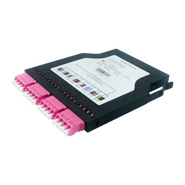
Fiber optic patch cables work based on the principle of total internal reflection. The core of the fiber acts as a waveguide, allowing light to travel through it by bouncing off the cladding. The light signals are transmitted through the core in the form of pulses, representing. The functioning of a fiber optic patch cord relies on its construction. It consists of a core with a high refractive index, enveloped by a coating featuring a lower refractive index. This assembly is fortified using aramid yarns and encased within a protective jacket. The core's transparency. Optical Fiber Patch Cords are designed to connect various optical devices and network components, facilitating high-speed data transfer across significant distances without degradation. They are an essential component of modern networking systems, enabling high-speed and reliable data transfer. They act as the critical link for interconnecting devices like optical switches, servers, and distribution frames. A bulk (multi-strand) fiber cable enters the patch panel and then each fiber strand is separated into individual strands or pairs of strands. This design allows the light to travel.
[PDF]
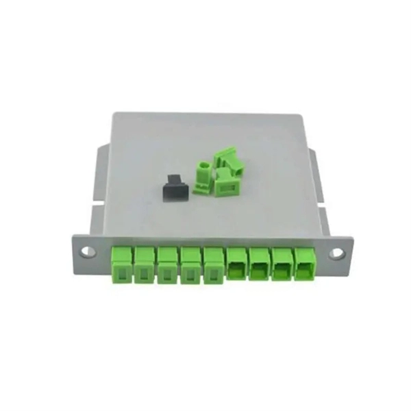
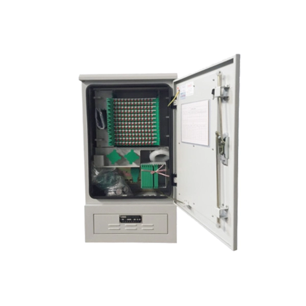
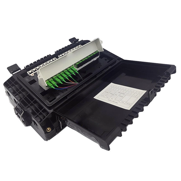
A fiber to Ethernet converter, often called a media converter, is a networking device that converts light signals from fiber optic cables into electrical signals used by Ethernet cables. This allows you to connect devices that use different types of cabling, such as a computer. An ONT, or Optical Network Terminal, is a device that converts fiber optic signals from your Internet provider into Ethernet signals that your devices can use. It's a key part of any Fiber to the Home (FTTH) setup. If your home uses cable Internet instead of fiber, you don't need an ONT. You'll use. For networking scenarios where the standard 100-meter reach of copper Ethernet cables (UTP or STP) is insufficient, Ethernet media converters for extended distance connectivity present a professional solution to extend connectivity. Connection Relationship: Step 1: Access outdoor fiber optic cables into fiber terminal box for the purpose of splicing the optical fiber cable and fiber optic.
[PDF]