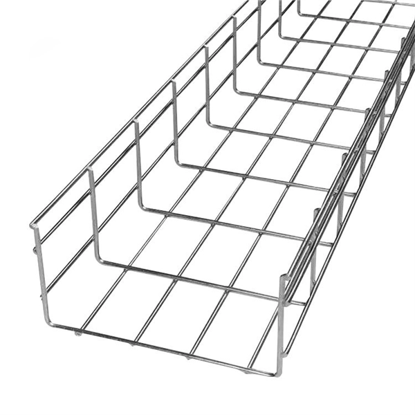
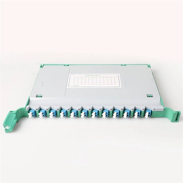
Fiber optic patch panels are enclosures that act as a distribution hub for fiber cable. A bulk (multi-strand) fiber cable enters the patch panel and then each fiber strand is separated into individual strands or pairs of strands. It acts as a hub for organizing splices and patch cords, streamlining fiber management and preserving signal integrity. These individual strands will then connect to electronic devices. A patch panel, including fiber patch panels and Ethernet patch panels, is a passive network device that centralizes, terminates, and organizes multiple copper or fiber cables. Serving as the interface between permanent cabling and active equipment, it provides clearly labeled ports that make. Structured cabling is a standardized system to help you organize and install the cables and hardware that connect your different devices to your network (including computers, servers, cameras, or any other smart gadgets). This article explores the structure, functionality, types, and benefits of fiber optic patch panels. What's the Fiber Optic Patch.
[PDF]

In this guide, we'll explore what protection relays are, how they're classified, the types available, and how they work with instrument transformers to create secure zones of protection. What Is a Protection Relay?. Protective Relay Definition: A protective relay is an automatic device that senses abnormal conditions in electrical circuits and triggers actions to isolate faults. Types of Protective Relays: Protective relays are categorized by their mechanism (electromagnetic, static, mechanical) and function. This article covers various types of protective relays, such as overcurrent, directional, and differential relays, highlighting their operating characteristics and applications in electrical systems. They don't just protect equipment; they ensure safety, prevent downtime, and save lives. A protective relay is a device that detects the fault and initiates the operation of the circuit breaker to isolate the defective element from the rest of the. The rectangular devices are test connection blocks, used for testing and isolation of instrument transformer circuits.
[PDF]

This document provides a comprehensive technical overview of the Ring Main Unit (RMU), serving as a reference for power system design, selection, and maintenance. Ring Main Units (RMU s) and Medium Voltage (MV) Switchgear are crucial in MV power distribution. Globally, they each hold about half the market share. MV switchgear handles primary distribution for large industrial facilities and grid infrastructure. RMUs, however, shine in secondary distribution. RMUs are commonly used in secondary distribution systems, particularly in urban areas, industrial complexes, and commercial. Scope of Application: The Ring Main Unit (RMU) is a compact switchgear device used in medium-voltage power distribution systems (typically 10kV–35kV). Some of the key features of the RMU includes SF6 gas insulation, compact and modular construction, integral protection system, fully extendable options. SFA-RM units are designed for supplying reliable energy, protecting electrical equipment in secondary distribution networks up to 17. Their compact design makes them suitable for various network applications such. Loading. Company Introduction:The New Concept Electric Inc. (NCE) was founded in October 2001, with a registered capital of 57 million Yuan. The company now covers an area of 77, 601 square meters (116 acres), and has a building area of 80, 451 square meters.
[PDF]
What is the cost of a relay coordination study in Singapore ? The cost of a protective device study in Singapore depends on the complexity of the electrical system, facility size, and number of relays. I2R, as a firm of Professional Engineers and Licensed Electrical Workers, is qualified under the Electricity Act to carry out all types of electrical testing and commissioning works to ensure that electrical apparatus are fit for power energization and safe for use and operation. We have all the. We are Specialized in Low Voltage Switchgears Testing, Commissioning, Maintenance and Installations from OEM's. We do factory Acceptance and Site Acceptance Testing and Commissioning support of LV Switchgears. Earth loop impedance measurments. Care Offers cost-effective solutions for protective device coordination in compliance with. Advance Engineering and Testing (AET) Pte Ltd established on 2019, is a top provider of electrical testing ranging from commercial, domestic, and industrial. The company provides 24/7 onsite support with prioritization of customer satisfaction. Their vision and mission statement is to continuously. The type of testing required for each specific relay needs to be designed with the goal of accomplishing the objective. We perform testing in four specific classes which. Our services are applicable to a number of industries such as Petrochemical industries, Oil and gas fabrication industries, Wafer fabrication plants, Pharmaceuticals.
[PDF]

One-line diagrams and detailed network data (lines, transformers, buses). Short-circuit models, including fault current calculations under various system configurations. Protective relay settings and coordination curves. Historical. presentation of protection and control relaying. The report will identify methodology behind these practices, present issues raised by the integration of microprocessor relays and the internal logic and external communication configurations, ying. Schematic diagrams of protection relays are essential tools for power engineers in the power generation, transmission, and distribution industry. This includes AC schematics and DC schematics and diagrams that prominently feature relaying. There are other equally important types of drawings that are not the subject. Power System Protective Relays: Principles & Practices Presenter: Rasheek Rifaat, P. Eng, IEEE Life Fellow IEEE/IAS/I&CPSD Protection & Coordination WG Chair Jacobs Canada, Calgary, AB rasheek. com IEEE Southern Alberta Section PES/IAS Joint Chapter Technical Seminar - November 2016. Recognized under 2(f) and 12 (B) of UGC ACT 1956 (Affiliated to JNTUH, Hyderabad, Approved by AICTE - Accredited by NBA & NAAC – 'A' Grade - ISO 9001:2015 Certified) Maisammaguda, Dhulapally (Post Via. Kompally), Secunderabad – 500100, Telangana State, India To introduce all kinds of circuit.
[PDF]
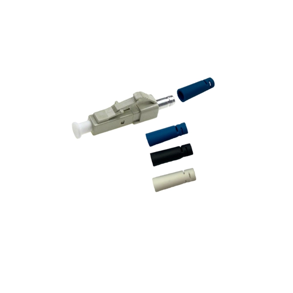
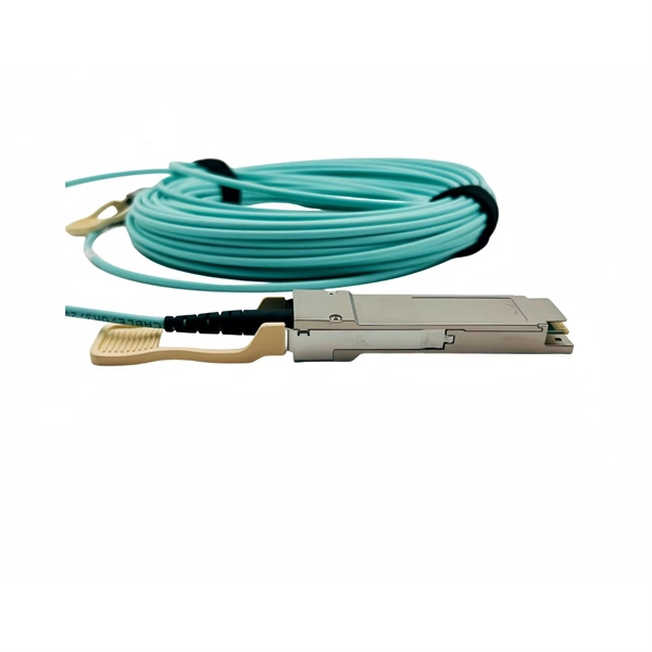
Mouser offers inventory, pricing, & datasheets for Duplex Fiber Optic Connectors. Check each product page for other buying options. QIANRENON LC Fiber Panel Mount Adapter LC Fiber Optic Connector Socket LC Fiber Coupler Module. XLR Panel/D-Panel Mount, for Fibre Optic Network LAN Integrated Cabling Need help?. Pricing (USD) Filter the results in the table by unit price based on your quantity. A tariff of 10% may be applied if shipping to the United States. A. Fiber Optic Connectors are the ends used to terminate optical fiber cable. The connector styles are DNP, ESCON, FC, FDDI, FSD, FSMA, LC, MPO, MT-RJ, MU, SC, SCRJ, SCRJ and Power Jack, SMA, ST, TNC, and VF-45. The mode options are multimode (OM1, OM2, OM3, OM4), POF, and Singlemode (OM1). These. High quality faceplates, RJ45 plugs, and copper, audio, video, and fiber optic modules from Molex, Leviton, CommScope, SignaMax, and more. COM supplies different types of fiber optic wall plates outlets, including angled ports fiber optic wall plate outlets. The angled opening provides a low profile and strain relief and allow fiber connectors and jumpers. Corning wall-plate outlet (WLL) is a highly configurable outlet product, available in both single- and double-gang configurations. It is designed for use within fiber-to-the-desk (FTTD) applications but may also be used to connect telephones and other peripherals to a network. A variety of fiber and.
[PDF]
In this video, we take you through the step-by-step installation of Optical Distribution Frames (ODF) and Optical Fiber Patch Panels—key components in setting up a robust fiber optic network. At Eman Communications, we specialize in delivering high-quality installations that ensure opt. more In. Fiber optic patch panels are mostly mounted in 19 inch relay racks, but they can also be mounted on freestanding rails, in cabinets and also on walls. The fiber optical patch panel is convenient for people to easily access the optical fiber cable in the panel. Keeping this page as a placeholder for now. Have any questions? Talk with us directly using LiveChat. An ODF is a centralized platform designed for terminating, cross-connecting, and managing optical fibers. It ensures fiber management is structured, minimizes signal loss, and provides accessibility for maintenance and future expansion. ODF Rack/Cabinet: Physical frame housing all terminations and. To connect fiber optic cables to a patch panel, users must follow a specific procedure that ensures proper connectivity and signal transmission. Here is a step-by-step guide on how to connect fiber optic cables to a patch panel. Step 1: Gather the Tools and Equipment The first step in connecting.
[PDF]
Please view our full RLH price list and contact us at info@fiberopticlink. com if you have any questions or special project needs. A fiber optic distribution panel (also known as a fiber distribution frame or FDF) serves as a centralized hub for managing, terminating, and distributing fiber optic cables in telecommunications and data networking systems. Fiber Adapter Panels fit all Multilink rack and wall mount Fiber Distribution Units. Panels are available in Simplex or Duplex adapter format. Patch panels are integral components of any network system. This equipment helps keep data systems and server rooms organized, functional and easily. Fiber optic patch panels are designed either to support direct termination or fusion splicing of the optical fibers. Fiber optic patch panels allow the optical splices of the fiber. Belden offers clean, simple, and lightweight Wall-Mount Panels within its DCX, FiberExpress (FX) UHD and ECX ecosystems. The versatile DCX Zero-U wall-mounting devices hold DCX cassettes and adapter frames and can be mounted under standard cable basket trays. The FX UHD and ECX modular platform of. UnitekFiber offers a wide variety of wall mounted fiber optic enclosures, including indoor fiber optic enclosures, outdoor rated fiber optic enclosures, plastic fiber optic enclosures or metal fiber optic enclosures. The wall mount fiber enclosure, also known as a wall mount fiber patch panel, is a.
[PDF]
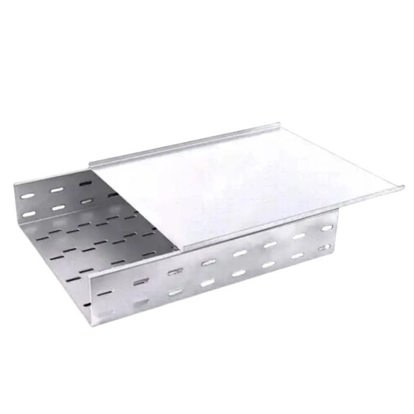
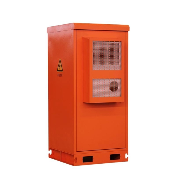
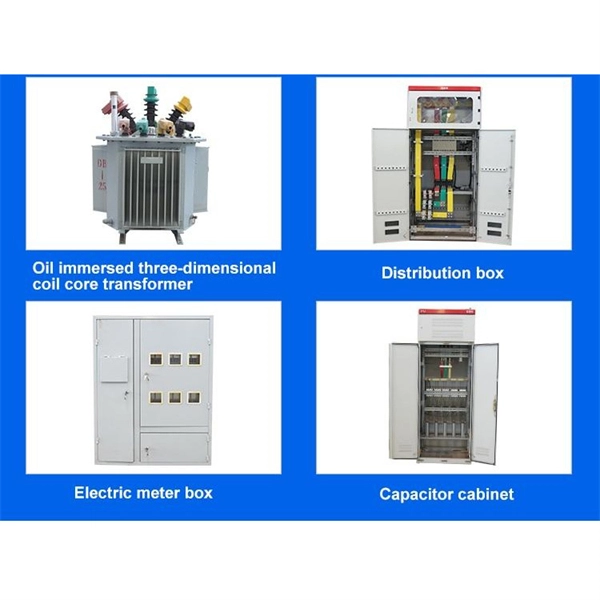
A distribution box, also known as a distribution panel or board, is a cabinet that holds electrical parts used to supply power to multiple circuits within a system. It acts as the central point where electricity distribution is managed inside a building. A distribution boxes is an essential device that manages the safe and efficient flow of electrical power throughout different areas of a building or facility. It is commonly used in homes, offices, and industrial settings to control and protect electrical circuits. Understanding its significance. The distribution panel, frequently called a breaker box or service panel, functions as the nerve center for a structure's entire electrical system. This metallic enclosure receives the incoming power supply from the utility company and organizes it for use throughout the building. From powering homes and industrial facilities to supporting medium-voltage infrastructure, these enclosures ensure safe, efficient, and reliable power distribution. Today, electrical systems are essential for homes and industries.
[PDF]
Use this Protection Relay Setting Calculator to calculate pickup current, time multiplier settings (TMS), operating time, coordination time interval (CTI), and plug setting multiplier (PSM) using fault current, CT ratio, and IEC 60255 curve parameters. of protective relays in terms of protecting high voltage lines. At the beginn ng of the article it is drawn up process to protect power lines. Consequently, it is shown the method of calculation for a particular power line a d performed the calculation for setting the distance protection. These calculations are critical in industrial. ve reliable and properly coordinated relay settings. Protection coordination refers to the systematic arrangement and interaction of protective devices within an electrical distribution network to ensure that faults are isolated in a controlled and orderly manner. The. With the help of these spreadsheets below, you can make your endless calculations much easier! Contact us for more information and download:.
[PDF]
High voltage relays are essential components in electrical systems. They control the flow of electricity in high voltage applications, enabling safe operations. These relays act as switches that open or close circuits. Their design ensures they handle high current levels without. Explore principles and configurations of protective relaying in high voltage systems. Ensure fast, selective fault clearance per IEC/IEEE standards. Protective relaying is the backbone of fault detection and system isolation in As transmission systems grow increasingly complex with integration of. A voltage protection relay system is a necessary component of any electrical setup. It prevents safety hazards and damage to equipment. It monitors voltage to determine if levels rise too high or dip too low. Many industries use voltage protection relay systems, especially those in high-voltage. Eaton's protective relays provide you with unique microprocessor-based devices that eliminate unnecessary trips, mitigate arc faults, protect motors and breakers, and provide system information to help you better manage your system. Our predictive diagnostic solutions include non-destructive testing. In electrical engineering, a protective relay is a relay device designed to trip a circuit breaker when a fault is detected. They are intended to quickly identify a fault and isolate it so the balance of the system continue to run under normal conditions.
[PDF]
This paper discusses some practical aspects of implementing single-pole tripping schemes in transmission-line protection. Implementation and techniques will vary in the design of protective relaying systems that i.
[PDF]
Definition of Protective Relay A protective relay is an automatic device that detects abnormalities in an electrical circuit and closes its contacts. This action completes the circuit breaker's trip coil circuit, causing the breaker to trip and disconnect the faulty section from the. Eaton's protective relays provide you with unique microprocessor-based devices that eliminate unnecessary trips, mitigate arc faults, protect motors and breakers, and provide system information to help you better manage your system. Our predictive diagnostic solutions include non-destructive testing. Here, Several circuit breakers in the fault current paths from the generators to the fault location have been tripped. Note that all generators- the power sources – have been disconnected. Therefore, the whole system has gone down, even though many circuit breakers have remained closed. The relay continuously monitors electrical parameters such as current, voltage, frequency, and phase angle. When these parameters deviate from normal operating conditions or. The rectangular devices are test connection blocks, used for testing and isolation of instrument transformer circuits. : 4 The first protective relays were electromagnetic. Protective Relays - Technical Seminar Nov 2016 - Copyright: IEEE 2 Abstract: Protective relays and devices have been developed over 100 years ago to provide “lastline”of defense for the electrical systems.
[PDF]
Then, according to the short-circuit current parameters, the relay protection of transmission lines, transformers, busbars, etc. is set, and the configured protections include current quick-break protection, gas protection, and longitudinal differential protection. Generator protection covers: phase-to-phase short circuits in stator windings, stator ground faults, inter-turn short circuits in stator windings, external short circuits, symmetrical overload, stator overvoltage, single- and double-point grounding in the excitation circuit, and loss of excitation. Explore principles and configurations of protective relaying in high voltage systems. Ensure fast, selective fault clearance per IEC/IEEE standards. Abstract: In this paper, the main electric wiring mode of 110kV. Relay protection is essential to ensure the stability, reliability, and safety of electrical power systems. In HV (High Voltage) and MV (Medium Voltage) substations, relay protection safeguards critical assets such as transformers, circuit breakers, and lines. Effective relay protection depends on. A protection relay is an intelligent device used to monitor electrical parameters such as current, voltage, frequency, and phase angle. Finally, a comprehensive.
[PDF]
Its main purpose is to safeguard electrical equipment like transformers, generators, and transmission lines from damage due to abnormal conditions such as overloads, short circuits, or voltage imbalances. A protective relay is an intelligent electrical device designed to detect faults in power systems and initiate corrective actions such as tripping a circuit breaker. It initiates the operation of circuit breakers to isolate the affected section. This prevents damage to equipment, reduces. Transmission lines are a vital part of the electrical distribution system, as they provide the path to transfer power between generation and load. Transmission lines operate at voltage levels from 69kV to 765kV, and are ideally tightly interconnected for reliable operation. In other words, the prime function of protective relays is the timely and. Many important issues, such as coordination of settings, operating times, characteristics of relays, mutual coupling of lines, automatic reclosing, and use of communication channels, are examined. Special protection systems, protection of multi-terminal lines, and single-phase tripping and. In electrical engineering, a protective relay is a relay device designed to trip a circuit breaker when a fault is detected.
[PDF]