A PoE (Power over Ethernet) switch is a network switch that delivers both power and data through a single Ethernet cable to connected devices such as IP cameras, VoIP phones, wireless access points, and IoT devices. This eliminates the need for separate power adapters, reducing cable clutter and. On this page you will learn what differentiates a PoE enabled switch from a regular LAN switch, when you should use a PoE switch versus a PoE injector and, what exactly is PoE (Power over Ethernet) technology. This allows network devices like IP cameras, wireless access points, and VoIP phones to receive power without needing separate electrical wiring. So, it is not only a. Michigan's trusted low voltage specialists since 2014, helping homeowners and businesses make smart connectivity decisions through expert installation and practical guidance. In today's blog, we'll explain what a PoE switch is and how it powers devices through one Ethernet cable. We'll also look at. PoE switches offer an efficient and cost-effective means of transmitting both power and data over one Ethernet cable; this guide will outline everything there is to know about them as well as their benefits, applications and how you can select the ideal switch for your needs. A PoE switch provides power and.
[PDF]
Connect the Ethernet cables: Connect one end of an Ethernet cable to the PoE switch's uplink port, and the other end to the network router or modem. Then, connect the devices that require power to the PoE ports on the switch using Ethernet cables. A Power over Ethernet (PoE) switch is a device that enables the transmission of both power and data over a single Ethernet cable. This eliminates the need for separate power cables and allows for flexible placement of network devices in locations where power outlets may be limited or absent. In. The first thing you need to do is connect your switch to an electrical outlet so it is powered on. This means you can power devices such as wireless access points, IP cameras, and VoIP phones using the same cable that provides network connectivity. 3at (PoE+), and. One of the biggest advantages of copper twisted pair Ethernet cable (also called Category cable) is it's ability to perform two critical functions at the same time: When these functions are simultaneously performed, it is known as PoE or Power over Ethernet. It utilizes efficient low-voltage 43 to 57 VDC over twisted-pair network cabling, such as Category 6A, Category 6, and Category 5e. This means PoE can be installed without risk to.
[PDF]
Yes, all Ethernet switches require electrical power to operate. Here's why: Active Electronics: Switches contain chips, processors, buffer memory, and power circuits that process and forward data. Power over Ethernet (PoE) is technology that passes electric power and data over twisted-pair Ethernet cable to wireless access points, IP cameras, and VoIP phones. This eliminates the need for separate power adapters, reducing cable clutter and. An Ethernet switch is a network device that connects multiple devices (computers, printers, servers, cameras, Wi‑Fi access points, etc. ) via Ethernet cables, enabling them to communicate over a Local Area Network (LAN). Unlike simple hubs that broadcast data to all ports, switches create a direct. Power Over Ethernet (POE) is a technique used for building wired Ethernet local area networks (LANs) which use Ethernet data cables instead of normal electrical power cords and wiring to carry the electrical current required to operate each device. Instead of needing separate power plugs for devices like cameras or sensors, a PoE switch powers them up while connecting them to the. PoE switches simplify this chaos by delivering both power and data through a single Ethernet cable, making installations cleaner and more efficient. They power essential devices like security cameras, access points, and VoIP phones without the need for extra wiring. This guide breaks down how PoE.
[PDF]
This data sheet describes the benefits, specifications, and ordering information for the Cisco Catalyst 9200 Series Switches. Default (Normal mode) : All ports can communicate with each other, VLAN (Secure mode): Downlink ports can communicate only with uplink ports. Enabling PD keepalive function, the switch will restart the IPC via PoE power when the IPC sends no message in a period of time, Extend (Surveillance mode):. New Taipei, Taiwan, May 19, 2025 - UFISPACE,a global leader in open networking solutions, has partnered with GIGABYTE to exhibit advanced data center switches at COMPUTEX 2025 (Booth No: K0802, Taipei Nangang International Exhibition Center, Hall 1). Featuring state-of-the-art Broadcom chipsets. Take advantage of limited-time promotions and offers on Cisco Catalyst Switching. Upgrade now and enjoy the savings. Cisco ® Catalyst ® 9200 Series switches extend the power of intent-based networking and Catalyst 9000 hardware and software innovation to a broader set of deployments. With its. PoE is a technology for wired Ethernet LANs to carry electric power required for the device in the data cables. 3af PoE standard provides up to 15. 4 W of power on each port. If you have switches. Max. PoE Power EXTEND (Surveillance mode): Transmission distance up to 250 meters. 3bt compliant devices such as IP cameras, VoIP phones, and wireless access points. When connecting network.
[PDF]
Power over Ethernet (PoE) is a technology that enables the transmission of electric current and data simultaneously over Ethernet cables, eliminating the need for separate power cables. This section wil.
[PDF]
The IEEE standard for the base PoE switches is 802. 3at for PoE+, and 802. PoE and PoE+ transmit power over two pairs of twisted-pair wires in their cables, while the PoE++ variants use four pairs of twisted-pair wires. The splitter is the silver and black box in the middle between the wiring junction box (left) and the access point (right). The PoE connection eliminates the need for a nearby power outlet. In another common configuration, the access point or other connected device includes internal PoE splitting. Power over Ethernet (PoE) switches combine data and power delivery into a single Ethernet cable, simplifying deployment of devices such as access points, IP cameras, VoIP phones, and IoT equipment. PoE does not reduce network speed, does not waste excessive power when proper cabling standards are. Therefore, everyone is concerned about whether PoE switches will affect speed. Key Benefits of Power over. PoE switches (Type 1) comply with the IEEE 802. 3af standard, which specifies the maximum power delivered over Ethernet cables.
[PDF]
This guide will equip you with a systematic approach to diagnosing and resolving the most common optical link performance issues. By understanding the root causes, you can minimize downtime and ensure your network operates at its peak efficiency. When issues like signal loss, slow speeds, or intermittent connectivity arise, systematic troubleshooting is key. Why Do Fiber Networks Fail? Despite their robustness, fiber networks can fail due to:. This document describes how to troubleshoot fiber optic interfaces by addressing some of the fiber optic module and cabling specifications. There are no specific requirements for this document. The information in this document is based on all Catalyst 9000 Series switches. This includes Doppler. Fiber optic troubleshooting is an essential skill for network administrators, technicians, and engineers responsible for maintaining and repairing fiber optic systems. I switched to ATT fiber from Xfinity because usually fiber optic is faster. However I've had fiber optic for 2 days, and my gateway is constantly disconnecting from the network. I know the technician said something about. Optical fiber networks are essential for delivering high-speed internet and reliable communication. Despite their advanced technology, these networks can encounter problems that impact performance. Effective troubleshooting is crucial to maintaining a smooth and efficient network. This blog post.
[PDF]
Quick Answer: To check CPU utilization on a Cisco switch, use the command “show processes cpu” in the CLI. This displays current CPU load, CPU usage history, and process-specific details, aiding in network performance troubleshooting. The CPU becomes too busy when either an IOS process consumes too much CPU time or the CPU receives too many packets from the switching hardware. When either of these two CPU consumers requires the CPU resource to the detriment of the other, then the CPU is too busy. For instance the CPU is. High CPU utilization on Cisco switches can lead to degraded network performance, packet loss, and even switch failures. Identifying and troubleshooting the root cause of high CPU usage is essential for maintaining a healthy network. In this article. I noticed that after having VLANs, ClearPass, spanning tree, and all other settings configured, that CPU util was just sitting at or above 85% on all these switches. I updated firmware to the latest version on all of them, but that didn't help. Problem analysis process 1. According to the switch logs, after searching for related processes, we can find that the. my switch core has high CPU usage every 3 minutes, switch logs attached. Do the outages/CPU spikes occur at the same time as the log entries appear such as : 00828 lldp:. Thank you, Fix the problem indicated.
[PDF]
Frequent status changes from up to down or vice versa in the ports logged by the switch port syslog indicates a port flap. On a big industrial plant we've replaced an old HP switch with a brand new couple of C2960x switches in stack configuration and ever since then, every 6/8 hours or so, the two fiber optics links of switch #2 go down at once. These are connected to a ring of 3 similar other access switches, that. EX4650 2-switch virtual chassis, running version 19. 2, optic p/n 740-031981 (SFP+-10G-LR) is plugged into port xe-0/0/10 and connected to an ISP via single mode fiber. Nothing special is configured on the port, it is running at 10G speed, show interfaces diagnostics optics shows that it's. This article describes steps to diagnose the Continuous port flapping on a FortiSwitch. Verify Cable Connection: Ensure the cable is properly connected between the switch port and the end device. Run the command below on FortiSwitch multiple times and check the. Real head scratcher this morning that I'm hoping someone can help me with! The port on our core switch (HP A5500) that our Smoothwall box is connected to keeps going up and down. Port flapping, also known as link flapping, causes a switch port's state to fluctuate between up and down within concise periods of time. This instability caused by flapping ports affects network connectivity. Port flapping is a common network issue that can disrupt communication between devices and degrade overall network performance.
[PDF]
Cisco announces the end-of-sale and end-of-life dates for the Cisco Catalyst 1000 Series Switches. The last day to order the affected product (s) is April 30, 2025. Tax included. This item is a deferred, subscription, or recurring purchase. By continuing, I agree to the and authorize you to charge my payment method at the prices, frequency and dates listed on this page until my order is fulfilled or I cancel, if permitted. Customers with active service contracts will continue to receive support from the Cisco Technical Assistance Center (TAC) as shown in. Intuitive software interface for effortless network configuration and monitoring. 8 x 1G ports Energy efficient 2 x 10G ports The NETGEAR 10-Port Gigabit/10G Ethernet Plus Switch (GS110EMX) is a versatile and efficient networking solution featuring 8 x 1G and 2 x 10G ports, designed for seamless. Cash On Delivery. Delivery All Over Lebanon. A 24-port, Layer 3 switch capable of high-power PoE++ output. Flexible 10 Gigabit connectivity for SME and SMB environments. Packet Forwarding Rate Buy online D-Link 24-Port Gigabit Stackable Smart Managed Switch with 10G Uplinks |DGS-1510-28XMP at ayoubcomputers. AYOUB. Discover the TP-Link Switches collection, providing efficient networking solutions designed to enhance connectivity and streamline your network infrastructure. These switches deliver reliable performance and advanced features, making them ideal.
[PDF]
The core switch functions as the central point of the entire network, forming the high-speed backbone for the organization's data infrastructure. Its primary purpose is to provide an optimized and reliable transmission structure for all aggregated data traffic. Simply put, it's the kingpin that keeps your network humming. You may also want to know: Can a Nintendo Switch Play DS Games? ·. A network switch connects multiple devices within a local area network (LAN) and directs data packets only to their intended destination. In large organizations, networks become complex, exchanging massive amounts of data. The core switch is the most important piece of hardware in this. A core switch is a high-capacity, high-performance Layer 3 switch positioned at the physical backbone of an enterprise network. Engineered to aggregate massive volumes of data from distribution switches, it provides ultra-low latency and maximum throughput to ensure uninterrupted routing and packet. A core switch is a crucial component of a network infrastructure that serves as the backbone of a network. It's a high-performance switch that provides high-speed connectivity between different network segments, which may include access switches, distribution switches, and routers. These switches are high-capacity, usually handling the greatest amount of traffic compared to other switches in the network. They primarily focus on speed.
[PDF]
In this video, we'll guide you through the process of configuring a Huawei Switch for your network. Whether you're setting up a new switch or optimizing your existing network infrastructure, this step-by-step tutorial will help you get the job done efficiently. This document provides campus networks typical configuration examples and feature typical configuration examples. "Campus Networks Typical Configuration Examples" provides typical campus network networking modes and a variety of deployment examples. This document is for switches running V200R003C00 and later. In this video, we'll guide you. Saving Configuration: Save changes to make the configuration permanent: Checking Settings: Use commands like display user-interface console 0 to verify correct configuration. Exiting the Device: Log out of the device after completing the configuration. Enabling Telnet Service and Granting Access on. The Combo interface, also known as the optical-electrical multiplexing interface, consists of two Ethernet ports (one optical and one electrical) on the device panel, and there is only one forwarding interface inside the device.
[PDF]
Most modern fiber-enabled network switches require an SFP transceiver module featuring a duplex (two strand) multimode OM3 or duplex single mode OS2 connection with LC connectors. Direct attach cables with pre-terminated SFP connections may also be used. Download the Application. CONFIGURING THE SWITCH IN DESIGO CC/CERBERUS DMS. CYBERSECURITY DISCLAIMER. 44. This tutorial will explain the steps required to configure fiber optics on a Cisco switch and ensure proper connectivity in your network. This chapter includes the following sections: •Information About Fibre Channel Interfaces, page 1-1 •Configuring Fibre Channel Interfaces, page 1-8 •Configuring Global Attributes for. : 192. 0 De livery of solutions fulfilling the Customers' multitude o. This document is intended to serve as a guide for architecting and deploying fiber optic networks in a customer environment. This installation planning guide describes some basic fundamentals of fiber optic technology, considerations for deployment, and basic testing and troubleshooting procedures. Fiber optic cabling is increasingly used to connect network switches and other datacom equipment, especially in long-distance and mission-critical applications. Fiber provides: Increased internet signal bandwidth.
[PDF]
For a three-way switch, two pigtails are generally connected to the common terminal: one for the incoming hot wire and one to extend the power to another device if needed. A simple switch does not need a neutral since the switch is interrupting the power feed only. Sometimes the power is run to the fixture box first and then a single 2 wire cable is brought down. In that instance. Traditional switches often require the home's circuit wires to be looped directly onto screw terminals, which can become a point of failure over time. Currently there are 10 ground wires spliced together if you include the 3 pigtails going to the switches. I haven't been able to open everything up and diagram. Each power conductor counts as 1. Pigtails do not count. 2nd. According to the National Electrical Code (NEC – United States) each item depending on the gage of wire Now take the number you came up with in the 1st column and multiply it by the cubic inch required [listed in 2nd column] for the. Pigtails act as bridges, allowing you to connect several wires to a single point without overloading connections. Professionals often prefer this method because it isolates issues, protecting downstream circuits from cascading failures. Why does this matter? Modern systems demand precision. For instance, if your circuit includes multiple wires feeding into a single outlet, pigtails create a reliable connection between the device and the circuit wires. This process prevents.
[PDF]
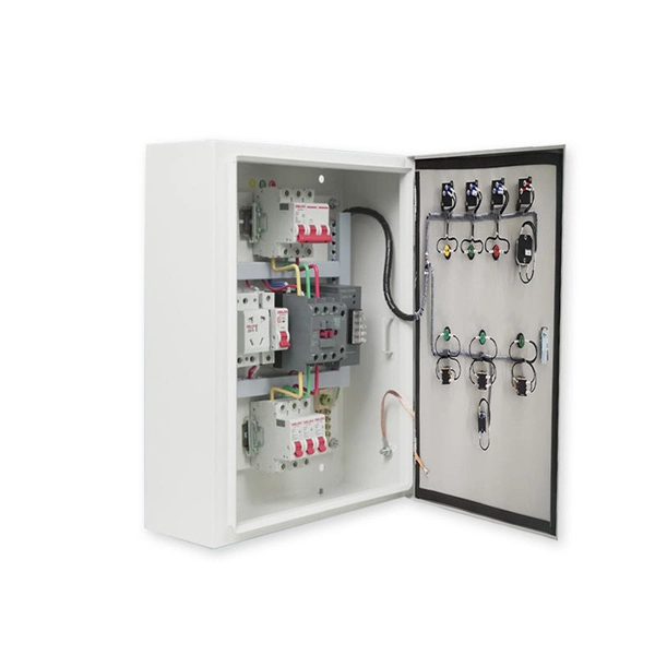
In Canadian service entrance panelboards the main switch or circuit breaker is located in a service box, a section of the enclosure separated from the rest of the panelboard, so that when the main switch or breaker is switched off no live parts are exposed when servicing the branch circuits.OverviewA distribution board (also known as panelboard, circuit breaker panel, breaker panel, electric panel, fuse box or DB box) is a component of an that divides an electrical power feed into subsidiary. North American distribution boards are generally housed in enclosures, with the positioned in two columns operable from the front. Some panelboards are provided with a door covering th. This picture shows the interior of a typical distribution panel in the United Kingdom. The three incoming phase wires connect to the busbars via a main switch in the centre of the panel. On each side of the panel are two.
[PDF]