This paper aims to study the design, simulation, and optimization of low-loss Y-branch passive optical splitters up to 64 output ports for telecommunication applications. For a waveguide channel profile, the standard material silica-on-silicon is used. Two important technologies for optical layer monitoring are Optical Performance Monitoring (OPM) and Optical Power Detection (OPD). Although they aim to maintain network health, they differ significantly in scope, technique, and deployment. This article delves into these differences, equipping. Optical Performance Monitoring (OPM) is considered a necessity over an optical network to enable sensibility of traffic line status and attain outstanding Quality-of-Service (QoS). The Y-splitters are designed and simulated at. Passive optical networks (PONs) are the network architecture of choice for residential fiber deployments. A PON is designed specifically to be cost-effective for delivering high data-rates to large customer populations. signals and various components of OPM functionalities are indispensable robust network operation and plays a key role flexibility and improve overall. Optical performance monitoring (OPM) is used for managing high capacity dense wavelength-division multiplexing (DWDM) optical transmission and switching systems in Next Generation Networks (NGN). OPM involves assessing the quality of data channel by measuring its optical characteristics without.
[PDF]
FBT splitters are more sensitive to fiber bending and environmental expansion, particularly under uneven thermal conditions. A beam splitter or beamsplitter is an optical device that splits a beam of light into a transmitted and a reflected beam. It is a crucial part of many optical experimental and measurement systems, such as interferometers, also finding widespread application in fibre optic telecommunications. a laser beam) into two (or sometimes more) beams, which may or may not have the same optical power (radiant flux). Different types of beam splitters exist, as described in the. Fiber optic splitters distribute optical power from one input fiber to multiple output fibers through either fused biconical taper (FBT) coupling or planar lightwave circuit (PLC) waveguide structures. Their performance depends on optical symmetry, waveguide integrity, and mechanical stability of. : The invention provides a light generating system (1000) comprising a first light generating device (110), a second light generating device (120), a luminescent material (200), a diffuser assembly (700), optical elements (500) comprising a first redirection optical element (1510), and a light exit. When splitting one incident light beam into two separate beams, beamsplitters are applied. Depending on the beam split based on intensity, wavelength, or polarization, its level of optical power on beam penetration differ. Just to mention few, these beamsplitter components are commonly required for.
[PDF]
Need some clarification about NEC 770. 47 (B), it says that the direct buried conductive fiber optic cable shall be 12 in (300 mm) away from the power cables. Separating high-voltage power cables from low-voltage communication cables is a fundamental requirement in any electrical installation. This practice is mandatory for two distinct reasons: ensuring the safety of the structure and its occupants, and preserving the integrity of sensitive data. Maintaining proper separation between power, data, and limited energy cabling is foundational to system performance, safety, and code compliance. Separation isn't just an EMI precaution — it protects signaling, reduces rework, and ensures pathways meet inspection expectations across risers. TECHNICAL GUIDELINE July 30, 2020 TG030 Rev. 4 Pathway Separation Between Telecommunication Cables and Power Cables Communications cables are, by design or necessity, often installed in close proximity and/or in the same pathway as power service cables. The electrical energy of the power cables can. This standard titled “Commercial Building Standard for Telecommunications Pathways and Spaces” is a joint publication of ANSI/TIA/EIA. Its current version (ANSI/TIA/EIA/-569-B) was published in October 1, 2004 and describes EMI aspects in Article 10. ca with numerous contributions by others. "UTP Separation Guidelines From EMI Sources". The values are the same as the cabling pathways standard, EIA-569, table 4.
[PDF]
Calibration & Repair services in Ireland. 5 day turn around with competitive pricing! View full electrical test and measurement equipment list here. is an independent calibration laboratory focused on meeting the total quality requirements of industry. Proper calibration of today's sophisticated test and measurement equipment is essential for preserving measurement accuracy, complying with international standards. Parameters covered include; Temperature, Humidity, Dewpoint, Various Gases, Pressure, Electrical, Weights & Scales, Analytical and some Specialist calibrations. Calibration is performed using the very latest Calibration Equipment/Standards & Calibration/Asset Management Software. Fast Efficient. PTM Calibration offers a wide range of services that complement our core business. We aim to be your one stop shop for all your calibration, test & measurement needs. From major blue chip companies & medium enterprises to small companies and sole traders. Including: aerospace, pharmaceuticals. OptiCal Sciences are an authorised service centre with service, repair and calibration experience and procedures for an extensive variety of models from a wide range of manufacturers.
[PDF]
It performs error detection and alarm monitoring, serving as an essential tool for bit error testing in R&D and production of optical modules/ devices. Bit Error Ratio Tester is an instrument used to test and analyze bit error ratio in digital transmission systems, fiber optic communication systems, and digital microwave communication systems. Dimension Technology's BERT800 bit error tester series offers a comprehensive solution for testing and verifying high-speed optical transceiver modules. OPTELLENT is a provider of broadband test and measurement solutions for communications. The Company's test & measurement solutions are used in product development, manufacturing. As transmission rates continue to accelerate, accurately measuring bit error rates in optical modules is crucial to ensure reliable performance. There are three interchangeable slot boards which include QSFP, SFP+ and SFP ports separately. QSFP, SFP+ and SFP ports follow QSFP MSA, SFP+ MSA and SFP MSA. The user interface allows you to individually monitor bit error rate, error count and timer by connecting to PC via USB cable. In high-speed digital communication systems, even the smallest bit-level error can compromise performance, reduce efficiency, or lead to costly rework.
[PDF]
Use this selector tool to quickly identify the best power supply for your aerospace and defense ATE requirements. Explore engineer-authored content and a vast knowledge base with thousands of learning opportunities. Use 25+ X-Series applications to analyze, demodulate, and troubleshoot signals across wireless, aerospace/defense, EMI, and phase noise. With extra memory and storage, these enhanced NPBs run Keysight's AI security and performance monitoring software and AI stack. Achieve fast, accurate board-level. Fiber-optic switches control light paths within fiber optics, ranging from simple on/off types to complex matrix configurations like 64×64. Fiber-optic switches are optical switches in the context of fiber optics. They're a core component in fiber-optic networks, where data travels as pulses of light through glass fibers. This technology allows for high bit rate transmission to be switched between various optical lines. All of these optical switches are purely optical path, there is no optical to electrical to optical conversion. Click to jump to class of switch --- Provides a bypass of.
[PDF]
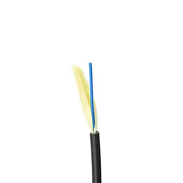
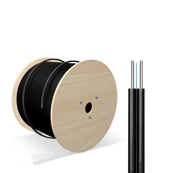
The majority of high-performance telecommunications fibers are manufactured using ultra-pure silica glass, which is silicon dioxide ($text {SiO}_2$). This material forms the two fundamental components of the fiber: the inner Core and the surrounding Cladding. An optical fiber, or optical fibre, is a flexible glass or plastic fiber that can transmit light from one end to the other. To ensure the light signal remains. Single-mode fiber is made from a super-thin fiber core of glass or plastic, through which only one ray of light can travel at a time. This makes it ideal for long-distance data transmission, as there is very little signal loss over distance. However, single-mode fiber requires specialized equipment. Fiber optic cables are made up of a core, cladding, and protective layers, with materials chosen based on the application requirements. What is an optical fiber? It's more than just a piece of glass or. An optical fiber is a single, hair-fine filament drawn from molten silica glass. These fibers are replacing metal wire as the transmission medium in high-speed, high-capacity communications systems that convert information into light, which is then transmitted via fiber optic cable.
[PDF]
This document discusses techniques for trenching and laying optical fiber ducts. Installing fiber optic cables underground involves far more than digging trenches and placing cables. It forms a critical backbone for modern communication networks across both urban and rural environments. Project success depends on careful planning, precise installation practices, and proper. Installing underground fiber optic cables is critical to establishing high speed internet infrastructure that delivers reliable connectivity for businesses nationwide. Fiber optic cables are the shining stars of modern connectivity, transmitting data at lightning-fast speeds through glass. This comprehensive guide walks through the essential steps and best practices for successful underground fiber optic cable deployment, ensuring optimal performance and longevity of your network installation. Why Choose Underground Fiber Optic Installation? Underground fiber optic installations. Placing cables underground has the added benefits of reducing transmission losses, aiding planning consent and reduced risk of service supply loss through extreme weather.
[PDF]
Optical isolators protect sensitive sources by blocking back-reflected light that could cause instability or damage. Optical circulators, meanwhile, manage directional routing through multiple ports, enabling duplex communication, optical path control, and compact system. of low-loss non-reciprocal fiber-based devices. Here, we present a solution to this issue by realizing low-loss (0. 81 dB), broadband (at least 50 GHz bandwidth) and high-extinction (up to 27 dB) circulators, based on Mach-Zehnder interfer meters including so-called fiber null-couplers. The latter. The ABSTRACT optical circulator is one of the key devices in the optical add-drop modules (OADMs) used in wavelength-division multiplexing (WDM) technology, which finds applications in large-capacity long-haul telecommunications systems. PM circulators. Faraday circulators (or less specifically optical circulators) are a kind of non-reciprocal optical devices. They are technically related to Faraday isolators, and on a broader scale similar to electronic circulators. Typically, a circulator has three or four optical ports (inputs / outputs). GKER Photonics Co. is really leading the charge in this area, providing key Optical Components that boost the reliability and performance of things like industrial fiber lasers and optical networks, not to mention data centers. If global suppliers take the time to understand what really.
[PDF]
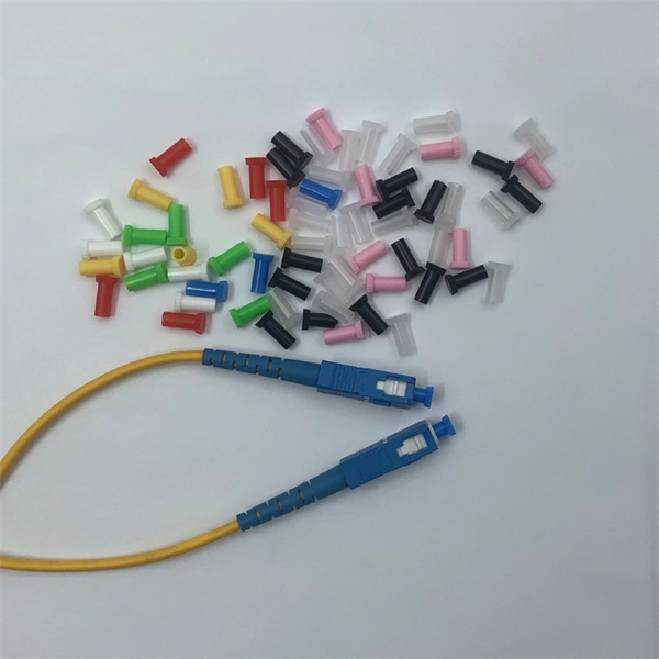
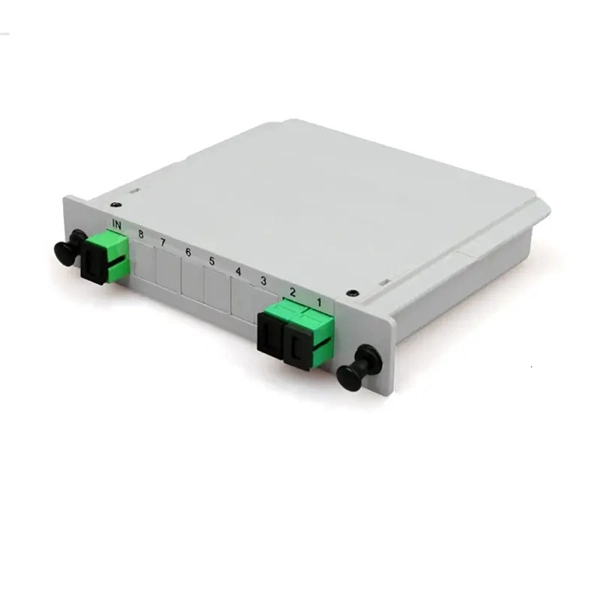
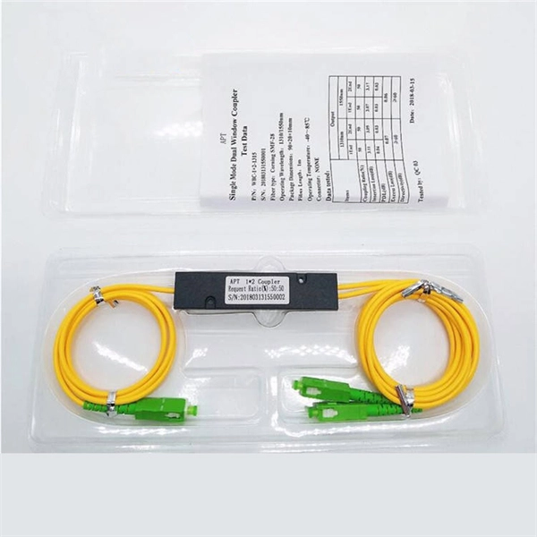
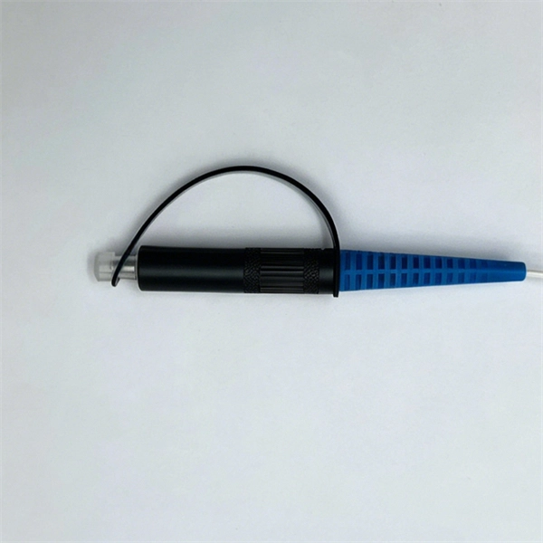
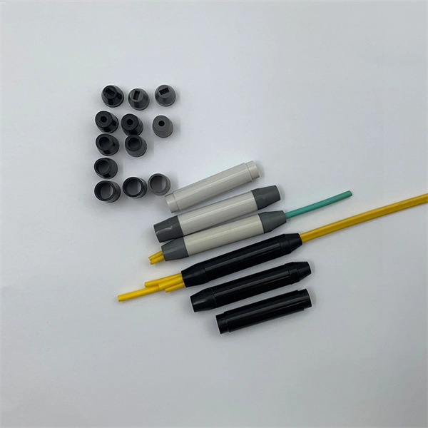
At its core, a fiber optic splitter relies on the principles of light reflection, refraction, and waveguiding to divide signals. Its design varies by type, but the underlying mechanism involves manipulating light to distribute its power across multiple output ports. A fiber optic splitter is a passive optical component that divides a single incoming optical signal into two or more outgoing signals, or combines multiple incoming signals into one. Their ability to efficiently manage optical signals makes them indispensable in various. This guide will demystify this pivotal passive device, exploring its types, working principles, and how it seamlessly integrates with optical transceivers to bring high-speed internet to your doorstep. 📄 What is an Optical Splitter? An Optical Splitter, also known as a beam splitter, is a passive. Fiber optic splitter is a passive optical device that includes multiple input and output ends. This principle allows a single input light beam to be split into N output light beams. The splitting can be achieved through two main methods: parallel beam splitting and beam divergence splitting. For example, an optical splitter.
[PDF]
A Thin-Film Filter (TFF) is an optical device that uses multiple layers of dielectric coatings deposited on a substrate to selectively transmit or reflect specific wavelengths of light. It is a fundamental component in modern optical communication systems. The Z-Block is a core optical component used in wavelength division multiplexing/demultiplexing (WDM) systems. Structurally, it is typically composed of several integrated optical elements, including collimating lenses, rhomboid prisms, and specially designed optical mirrors. TFFs are widely used as. The Process Technology of Optical Coating: Applications of TFF in Optical Communication Optical coating technology has revolutionized the way we enhance the performance and durability of optical devices, particularly in optical communication systems. As the demand for high-speed internet and. WDM (Wavelength Division Multiplexing) is a technology that expands the optical fiber transmission bandwidth and improves network transmission capacity by transmitting multiple optical signals of different wavelengths in the optical fiber. TFF (thin film filter) and AWG (arrayed waveguide grating). A thin film resonant cavity filter (TFF) is a Fabry-perot A cavity is formed by using multiple reflective dielectric thin film layers. The TFF works as bandpass filter, passing through specific wavelength and reflecting all other wavelengths. The cavity length decides the passing wavelength.
[PDF]
This report provides a comprehensive assessment of recent tariff adjustments and international strategic countermeasures on Optical Modules cross-border industrial footprints, capital allocation patterns, regional economic interdependencies, and supply chain reconfigurations. Global Optical Modules Market Size By Product Type (Transceivers, Transponders), By Technology Type (Single-Mode Fiber (SMF), Multi-Mode Fiber (MMF)), By Application (Telecommunications, Data Centers), By Data Rate (10 Gbps, 25 Gbps), By Form Factor (SFP (Small Form-Factor Pluggable), SFP+. The global market for Optical Modules was estimated to be worth US$ 17590 million in 2024 and is forecast to a readjusted size of US$ 56786 million by 2031 with a CAGR of 15. 8% during the forecast period 2025-2031. The potential shifts in the 2025 U. 7% during the forecast period MARKET INSIGHTS The global Optical Module Package Market was valued at 8942 million in 2024 and is projected to reach US$ 20220 million. Get a sneak peek into the valuable insights and in-depth analysis featured in our comprehensive optical module integration market report. Download now to stay ahead in the industry! Need more tailored information? Ketan is here to help you find exactly what you need. Get a sneak peek into the.
[PDF]
Short answer: Usually yes, you use them in pairs, but the “pair” can be a media converter on one end and a fiber switch (or SFP in a switch) on the other, as long as both sides speak the same speed, wavelength, and optical mode. Mixing single-mode and multi-mode transceivers creates major optical and hardware problems. This leads to unreliable network performance. Here's why: Light source & beam profile: SM lasers are narrow and Coherent; they couple efficiently into a 9 µm core. MM VCSELs/LEDs produce a broader beam. Single-mode optical modules are best for long distances and fast speeds. They use a thin fiber core. Picking the right optical module depends on your network needs. The sfp transceiver single mode typically utilizes laser diodes as the light source and operate at wavelengths of 1310nm or 1550nm. The key is opposite directions use opposite wavelengths, so A must face B—AA or BB will not work. Other BiDi pairs exist (e. Single-mode fibers support a wide band and large transmission capacity, and are used for long-distance. o In optical modules, "core" refers to the light-transmitting channel in the fiber. A 1-core module uses a single fiber core for data transmission, while a 2-core module uses two cores. o Think of a highway. A 1-core fiber is like a single-lane road—only one car (or data signal) can travel at a.
[PDF]
Low Attenuation: G655 fibers have low signal loss over long distances due to their low attenuation coefficient. This allows for efficient transmission without significant degradation or amplification requirements. This Recommendation describes the geometrical, mechanical, and transmission attributes of a single-mode optical fibre which has the absolute value of the chromatic dispersion coefficient greater than some non-zero value throughout the wavelength range from 1530 nm to 1565 nm. This dispersion. This specification covers Optical Ground Wire Cables (OPGW) for the installation on high voltage overhead power lines. The cable contains optical fibers for data transmission and telecom purposes and is installed instead of a ground wire. The specification describes the basic design of an. G. 657 are ITU-T standardized singlemode fiber types used across long-haul, metro, ODN, and FTTH networks. Each fiber type is engineered with different refractive index profiles, dispersion properties, and bending performance to support specific applications—from long-distance. The optical fibres are made of a high grade doped silica core surrounded by a silica cladding; they are coated with a dual layer of UV cured acrylate based coating. This single mode fibre supports high-power signals and longer distances, as well as closely spaced DWDM (dense WDM) channels at rates.
[PDF]
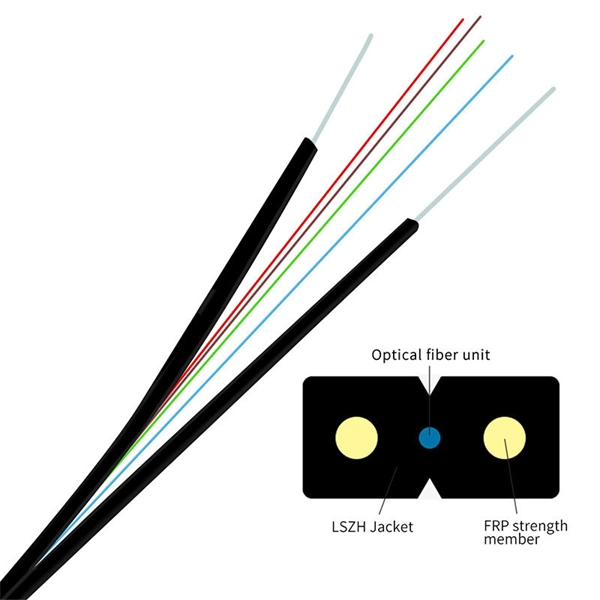
Optical fiber consists of a and a layer, selected for due to the difference in the between the two. In practical fibers, the cladding is usually coated with a layer of or. This coating protects the fiber from damage but does not contribute to its properties. Individual coated fibers (or fibers formed into ribbons or bundles) then ha.
[PDF]