Positive busbars, which collect all positive connections. Key Steps: When wiring a pair of 12V busbars, connect the positive terminal of each load to a stud on the positive busbar and their negative terminal to a stud on the negative busbar. 5' above batteries on inside of cockpit combing below decks. Install one new positive bus bar beside the negative one separated by about two inches 3. Positive and negative busbars are physically identical apart from the red/black colours used by some manufacturers to visually differentiate between. A Complete Guide to Battery Terminal Connector Types The store will not work correctly in the case when cookies are disabled. JavaScript seems to be disabled in your browser. For the best experience on our site, be sure to turn on Javascript in your browser. Skip to Content Blog Sign In Create an. This image illustrates a standard car battery with top post terminals and labeled connectors for the positive (+) and negative (–) ends, emphasizing safe and correct installation. A battery terminal connector is a fitting or clamp that attaches to a battery's terminal to connect a cable. In other. Both positive and negative terminals are the soul of the electrical system of the car, allowing the engine to start while keeping other components running. The catch? Mix-up or loose connection can cause electrical failure, drained batteries, and damage to wiring. This blog guides you how the two.
[PDF]
If a fault is detected, the relay will send signals to adjacent relays and circuit breakers, allowing the closest breaker to trip first while other breakers delay their operation. This selective coordination helps isolate the faulted zone while maintaining the power supply to the. A protection relay is a crucial component of electrical systems that safeguard infrastructure, employees, and equipment from electric problems and malfunctions. It functions as a watchdog by constantly surveying multiple system components including voltage, current, frequency, and phase angle. It. A protective relay is the vigilant guardian of electrical networks, constantly monitoring and analyzing electrical parameters to detect abnormal events. Acting as the first line of defence, it swiftly detects faults, such as short circuits or overcurrents. It triggers protective actions to isolate. In electrical engineering, a protective relay is a relay device designed to trip a circuit breaker when a fault is detected. : 4 The first protective relays were electromagnetic devices, relying on coils operating on moving parts to provide detection of abnormal operating conditions such as. A protective relay is an intelligent device that senses abnormal electrical conditions, such as overcurrent, under-voltage, or frequency deviations. It initiates the operation of circuit breakers to isolate the affected section.
[PDF]

A protection relay tripping circuit connects relays to breakers for fast fault isolation. Key components include trip/close coils and anti-pumping relays. Proper design, testing, and maintenance ensure reliable overcurrent, differential, and auto-reclosing protection in power. The protection relay tripping circuit refers to the critical electrical control loop that executes trip/close commands from protective relays to circuit breakers, ensuring rapid fault isolation in power systems. Essential. Electromechanical protective relays at a hydroelectric generating plant. The relays are in round glass cases. In electrical engineering, a protective relay is a relay device. A protective relay is an intelligent electrical device designed to detect faults in power systems and initiate corrective actions such as tripping a circuit breaker. Its main purpose is to safeguard electrical equipment like transformers, generators, and transmission lines from damage due to. By definition, a protective relay is a switchgear device that detects faults and initiates the circuit breaker operation to isolate the problematic component of the system. Electrical values are measured by these relays to determine abnormal circumferences of a circuit. It functions as a watchdog by constantly surveying multiple system components including voltage, current, frequency, and phase angle.
[PDF]
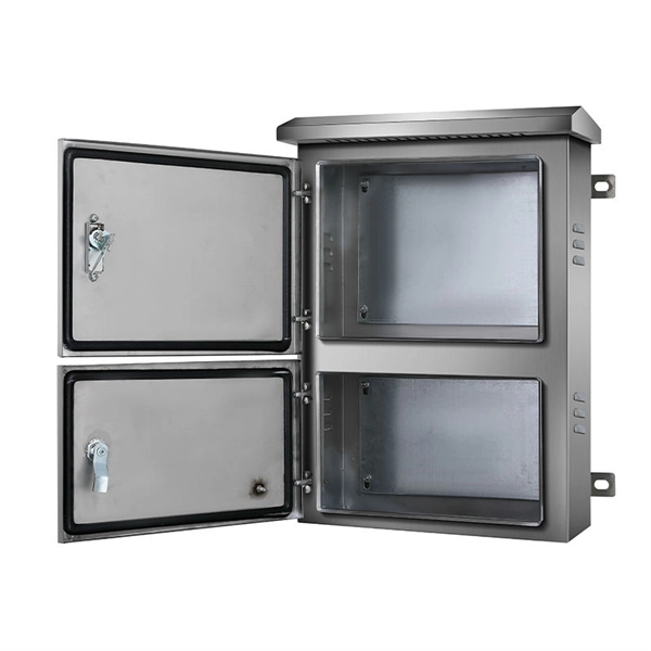
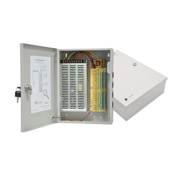
At AES Power Solutions, we provide comprehensive lightning protection solutions engineered to shield your infrastructure, equipment, and personnel from the dangers of lightning strikes and electrical surges. An essential electrical component for properly distributing electricity to lighting systems in dangerous areas with explosive gasses, vapors, or combustible dust is the Explosion Proof Lighting Distribution Box. It is extensively utilized in sectors where stringent safety regulations are. BXM (D)8050 Series Explosion Proof. ◆ The explosion-proof illumination distribution boxes is equiped with compound design: Combines flameproof (Ex d) and increased safety (Ex e) chambers for flexible protection. Our LPS products include: Lightning rods: Also known as air terminals, these are metal rods placed at the highest point of a structure. Grounding systems: These provide a. Our robust distribution boxes are engineered to provide efficient and reliable power management for a wide range of applications. Designed with high-quality materials and advanced safety features, these distribution boxes ensure the safe and organized distribution of electrical power in. 1This is a technical guideline for the purposes for carrying out remediation. It is therefore RSC's Standard. The RSC adopted the technical guidelines from local and international technical Standards and international best practices. The Building Standard developed by the.
[PDF]
Earth fault protection based on measured or calculated residual current values: If a breaker fails to be triggered by a tripping order, as detected by the non-extinction of the fault current, this backup protection sends a tripping order to the upstream or adjacent breakers. In electric power systems and industrial automation, ANSI Device Numbers can be used to identify equipment and devices in a system such as relays, circuit breakers, or instruments. The device numbers are enumerated in ANSI / IEEE Standard C37. 2 Standard for Electrical Power System Device Function. In North America protective relays are generally referred to by standard device numbers. ANSI IEEE Standard Device Numbers are below: (the more commonly used ones are in bold) 86T is a Lockout Relay for a. The ANSI standard device numbers ( As per ANSI/IEEE standard C37. 2) are used in the design of an electrical power system. The list of ANSI device numbers with their acronyms is as given below. Save my name, email. The protection and control devices in electrical equipment can be referred to by numbers, with appropriate suffix letters when necessary, according to the functions they perform. Even in those parts of the world where IEC standards are predominate, the use of ANSI numbering. There are two methods for indicating protection relay functions in common use. The functions are supplemented by letters where amplification of the function is required. The other is given in IEC 60617 and uses.
[PDF]

The standard industry practice is to set overload relays at 125% of the motor's nameplate Full Load Ampere (FLA) rating. Plug Setting Multiplier (PSM) indicates how many times the determined relay secondary current (typically the CT secondary) exceeds the relay pickup (plug) current. It is the key quantity utilized in IDMT (inverse definite minimum time) curves to calculate the basic operating time. PSM (Plug Setting. An overload relay is a crucial device for motor control, designed to prevent motors from overheating or suffering winding damage due to excessive current. Motor overload relays protect against sustained overcurrent conditions that cause dangerous overheating, insulation breakdown, and premature. Overload relays protect motors and equipment from thermal damage caused by prolonged overcurrent conditions. IEC 60255 defines standards, formulas, and performance requirements, enabling accurate calculations and real-world applications. How is the overload relay current calculated? Why include. Setting motor overload relays correctly is critical for protecting AC induction motors from sustained overcurrent conditions while avoiding nuisance trips during normal starting transients. This occurred when the relay F was set at 1. The complaint was that the relay tripped instantly on overload when the thermal damage curve show plotted for a specific current that was less t an.
[PDF]
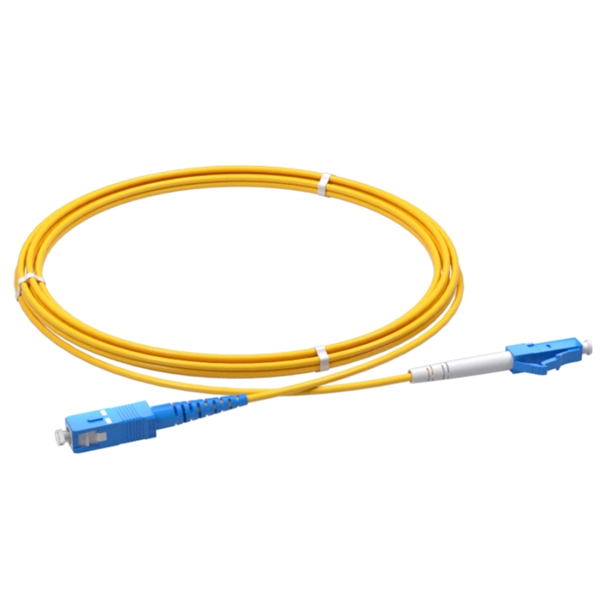
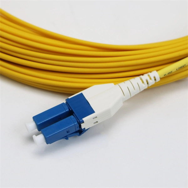
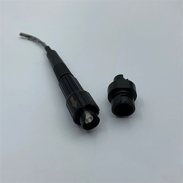
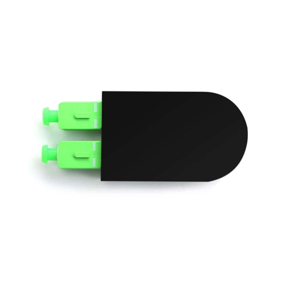
Temukan daftar Supplier, Pabrik, Importir, Distributor dan Toko Kabel Patch Cord untuk wilayah Indonesia . Update setiap hari, harga kompetitif dan layanan terpercaya. High performance and high quality connectors cable assembly are required for next generation optical networks to assure long term reliability for demanding applications such as FTTx, DWDM, 100G, CATV and etc. The connector assemblies are IEC, Telcordia and RoHS compliant. The termination passed. Prima Akses Digital Indonesia, is a Indonesian local company specialized in fiber optic product development and solution service for network infrastructure. Prima Akses Digital Indonesia, established in 2020, is supported by several partner companies and management which have been experienced in.
[PDF]
Thermal overload relays are widely used to protect motors. These devices work on the thermal effect principle. A thermal relay is an electromechanical device that detects temperature changes in electrical circuits, protecting equipment from overload and overheating. Thermal relays are critical components in electrical systems, designed to protect motors and other electrical equipment from damage caused by. Thermal Relay Definition: A thermal relay is defined as a device that uses the unequal expansion rates of metals in a bimetallic strip to detect overcurrent conditions. Working Principle: The thermal relay operates by heating a bimetallic strip, causing it to bend and close normally open contacts. So, the thermal relay is one of the types of the relay, used to provide complete safety against single phasing, unbalanced voltages & overloads. Thermal relays are the perfect solution for providing protection to motors which provides the most precise tripping for the electric motor during single. Introduction — The Core Device Protecting Industrial Motors Thermal overload relays are one of the most essential protection components in industrial motor circuits. Correct understanding and configuration ensure equipment safety and longevity. Its performance matches the actual heating characteristics of.
[PDF]

The SEL-221F Relay uses positive-sequence memory voltage polarized mho distance elements for phase and ground distance protection. These elements expand in proportion to the source impedance to provide more resistive fault coverage than self-polarized mho elements. VAMP 221 arc protection system components. Central unit VAMP 221. I/O units VAM 12L / VAM 12 LD, VAM 10L / VAM 10LD, VAM 3L / VAM 3LX and VAM 4C / VAM 4CRL / VAM 4CD 10 1. Arc sensors VA 1 DA, VA 1 EH, ARC SLx. Schneider Electric VAMP range is an arc flash detection and protection pioneer offering fast and reliable devices to improve safety. VAMP 221 significantly reduces the risk of potential personal damage, and material and production losses caused by arc fault. VAMP 221 complies with the latest standards concerning the. Serial communications ports allow local or remote interaction with the relay. 5” high chassis sizes. The report will identify methodology behind these practices, present issues raised by the integration of microprocessor relays and the internal logic and external communication configurations, ying. In the design of electrical power systems, the ANSI Standard Device Numbers denote what features a protective device supports (such as a relay or circuit breaker).
[PDF]
This forces distribution transformers to be located within several hundred feet of each customer, but eliminates the reliability concerns associated with T-splices that are required to connect underground servic.
[PDF]

What is the cost of a relay coordination study in Singapore ? The cost of a protective device study in Singapore depends on the complexity of the electrical system, facility size, and number of relays. I2R, as a firm of Professional Engineers and Licensed Electrical Workers, is qualified under the Electricity Act to carry out all types of electrical testing and commissioning works to ensure that electrical apparatus are fit for power energization and safe for use and operation. We have all the. We are Specialized in Low Voltage Switchgears Testing, Commissioning, Maintenance and Installations from OEM's. We do factory Acceptance and Site Acceptance Testing and Commissioning support of LV Switchgears. Earth loop impedance measurments. Care Offers cost-effective solutions for protective device coordination in compliance with. Advance Engineering and Testing (AET) Pte Ltd established on 2019, is a top provider of electrical testing ranging from commercial, domestic, and industrial. The company provides 24/7 onsite support with prioritization of customer satisfaction. Their vision and mission statement is to continuously. The type of testing required for each specific relay needs to be designed with the goal of accomplishing the objective. We perform testing in four specific classes which. Our services are applicable to a number of industries such as Petrochemical industries, Oil and gas fabrication industries, Wafer fabrication plants, Pharmaceuticals.
[PDF]
In the ring distribution network, differential relays, which rely on communication between the protection relays, are used for the underground cable protection. To guarantee cable protection when communication is failed, an auxiliary protection by using directional overcurrent. The use of ring circuits in 6 – 35 kV distributed electrical networks can improve the reliability of power supply. An increase in the load power and the share of distributed generation and renewable energy sources causes the redistribution of the power flow during the operation of an electrical. The selected protection principle affects the operating speed of the protection, which has a significant im-pact on the harm caused by short circuits. The faster the protection operates, the smaller the resulting ha-zards, damage and the thermal stress will be. Further, the duration of the voltage. ABSTRACT: Over current protection is the simplest form of power system protection of distribution line. In. The purpose of this study is to investigate the coordination of overcurrent relay in different types of the distribution network, which are radial, ring, and interconnected distribution system during line to ground fault occurrence at the bus. Usually, this refers to medium-voltage networks, since they are protected by numerical relay devices, as opposed to low-voltage networks, where utility operators allocate.
[PDF]
Every protection system which isolates a faulty element is required to satisfy four basic requirements: (i) reliability; (ii) selectively; (iii) sensitivity; and (iv) speed of operation. Protection system is an extremely important part of the power system as it is provided to operate under abnormal conditions to prevent failure or isolate trouble and limit its effect. It is designed to detect and isolate faults or abnormal conditions within the system to prevent damage, minimize downtime, and maintain power quality. This. Relay protection primarily operates on the principle of utilizing the variations in electrical quantities (such as current, voltage, power, frequency, etc. It emphasizes selectivity, coordination, fault response, and system behavior rather than individual relay devices. Relay protection is often misunderstood as a. Protective relays and devices have been developed over 100 years ago to provide “lastline”of defense for the electrical systems. They are intended to quickly identify a fault and isolate it so the balance of the system continue to run under normal conditions. The selection and applications of. Abstract: Information on the concepts of protection of ac transmission lines is presented in this guide. Many important issues, such as coordination of settings, operating times, characteristics of.
[PDF]
Relays may be fitted with a "target" or "flag" unit, which is released when the relay operates, to display a distinctive colored signal when the relay has tripped.OverviewIn, a protective relay is a device designed to trip a when a is detected. The first protective relays were electromagnetic devices, relying on coils operating on moving par. Electromechanical protective relays operate by either, or. Unlike switching type electromechanical with fixed and usually ill-defined operating voltage thresholds. Electromechanical relays can be classified into several different types as follows: "Armature"-type relays have a pivoted lever supported on a hinge or knife-edge pivot, which carries a moving contact. These relays may.
[PDF]
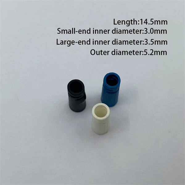
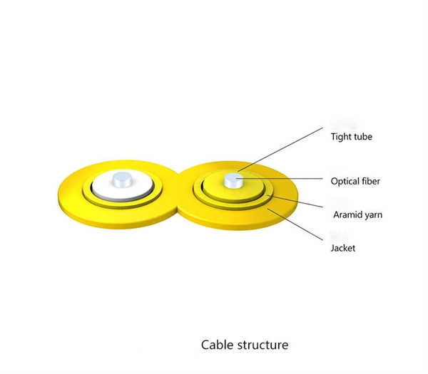
Main cost drivers include cable grade (indoor vs outdoor, armoured), distance, and labor for trenching, splicing, and termination. This guide presents ranges in USD and practical price estimates to help budget planning. Indoor OM3/OM4 vs outdoor armoured increases price. This guide outlines the major factors that influence fiber optic cable costs and provides practical tips for estimating pricing in bulk or project-based scenarios. Content 1 What's the Typical Price Range? 2 1. Fiber Count and Cable Construction 3 2. Fiber-optic cable materials typically cost $1 to $6 per linear foot, depending on fiber count and cable type. Commercial building installations with 100-200 network drops generally range from $15,000 to $30,000. Single-mode fiber costs less per foot than multimode fiber, but it requires more. Buyers typically pay for fiber optic cable by length, fiber type, and installation complexity. Fiber. The fiber optic cable protection tube market was valued at $1. 8 billion in 2023 and is expected to exceed $2. 1 mm diameter, containing 90 fire-resistant, flexible, and robust conduits.
[PDF]