These characteristics make DST splitters suitable for optical benches and reference measurement systems, where lasers with low to medium power are split into multiple beams with minimal loss. DST beam splitters are designed for unpolarized light sources. A beam splitter or beamsplitter is an optical device that splits a beam of light into a transmitted and a reflected beam. It is a crucial part of many optical experimental and measurement systems, such as interferometers, also finding widespread application in fibre optic telecommunications. Beamsplitters are often classified according to their construction: cube or plate. Signal attenuation refers to the reduction in the intensity of a light beam as it passes through a medium or a device. When a beam splitter divides the incoming light. The Keysight Technology, Inc. family of high-performance beamsplitters offers industry-leading polarization and beam control with low wavefront distortion. For more than 35 years, Keysight has designed and produced beamsplitters exclusively for the most demanding custom interferometry applications. Cube beamsplitters avoid beam displacement by working at 0° angle of incidence and placing the coated surface between two right angle prisms, but power handling can be limited if epoxy is used to bond the prisms. Newport offers a wide variety of Beamsplitters in various shapes.
[PDF]
Passive media components such as cables, cable splices, and connectors cause attenuation. Although attenuation is significantly lower for optical fiber than for other media, it still occurs in both multimode and single-mode transmissions. Two fundamental mechanisms cause attenuation inside the fiber itself: absorption and scattering. These are intrinsic to the glass, meaning they exist even in a perfectly manufactured, perfectly installed fiber. Scattering is the bigger factor at the wavelengths most networks use. The silica glass. Optical attenuation is the gradual loss of flux (light intensity) as an optical signal travels through a fiber. Measured in decibels (dB), it's the logarithmic ratio of the output power to the input power. Every network has a "loss budget". F iber optic networks rely on the efficient transmission of light signals to deliver high-speed data over long distances. However, various factors can cause signal degradation, leading to performance issues and reduced network reliability. You may see slower speeds and less steady connections when signal loss goes up. Things like impurities in the fiber core and reflections at the core-cladding edge cause this drop. This can be due to a variety of factors: scattering and absorption, intrinsic. Signal attenuation in fiber optics is a key concept in telecommunications. It affects how far a signal can travel without losing.
[PDF]
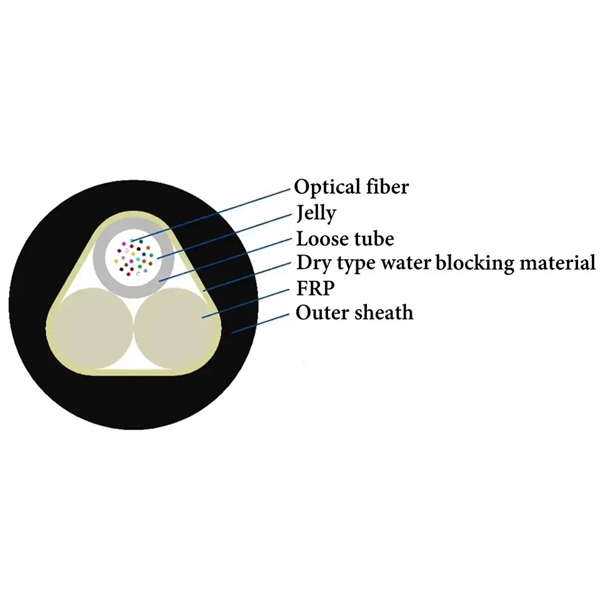
Even when splicing identical fibers together, if they are not perfectly aligned, optical power will be lost and attenuation across the splice will exist. The performance of a fiber optic splice is determined by a number of factors, including the quality of the fiber, the cleanliness of the splice, and the techniques used to make the splice. Intrinsic factors, such as the refractive index of the fiber, are those that are inherent to the fiber itself. Fiber optic cable splicing is the process of joining two fibers end-to-end to create a continuous optical path. In PON and FTTx networks (e., FTTH, FTTP, FTTM), splicing is essential for extending cables, repairing breaks, or connecting backbone and distribution lines. To protect these vulnerable. Fiber loss, also called fiber optic attenuation or attenuation loss, refers to the loss of signal between input and output. Losses can be introduced by various means such as intrinsic material absorption, scattering, bending, connector loss and more. The absorption is caused by the absorption of the light and conversion to heat by molecules in the glass. Primary absorbers are residual OH+ and dopants used to modify the refractive index of the glass. Unlike using connectors, which are designed for frequent connection and disconnection at patch panels, splicing creates a permanent, stable joint with minimal light loss. This process is fundamental to building and.
[PDF]
Beer-Lambert law describes the relationship between the absorbance of light by a substance, the concentration of the substance, and the path length of the light through the sample. ² In spectrophotometry, this law plays a fundamental role in quantifying the concentration of a solute in. Spectrophotometry is a technique used to measure how much light a substance absorbs at different wavelengths. When light passes through a sample, the molecules in the sample absorb some of it, and the rest passes through. The basic principle is that each compound absorbs or transmits light over a certain range of wavelength. This measurement can. Spectrophotometry is a branch of electromagnetic spectroscopy concerned with the quantitative measurement of the reflection or transmission properties of a material as a function of wavelength. Spectrometers use light wavelengths to investigate the chemical composition of a sample. Atomic spectrometers use an analytical method by which one or several elements in unknown mixtures can be detected.
[PDF]
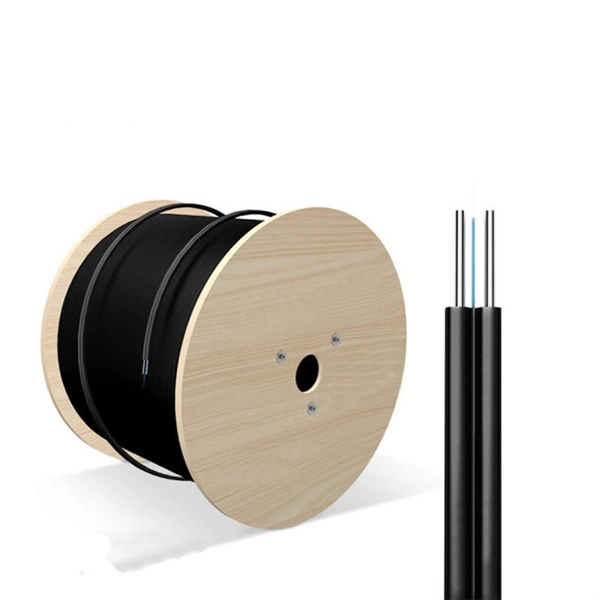
Low Attenuation: G655 fibers have low signal loss over long distances due to their low attenuation coefficient. This allows for efficient transmission without significant degradation or amplification requirements. This Recommendation describes the geometrical, mechanical, and transmission attributes of a single-mode optical fibre which has the absolute value of the chromatic dispersion coefficient greater than some non-zero value throughout the wavelength range from 1530 nm to 1565 nm. This dispersion. This specification covers Optical Ground Wire Cables (OPGW) for the installation on high voltage overhead power lines. The cable contains optical fibers for data transmission and telecom purposes and is installed instead of a ground wire. The specification describes the basic design of an. G. 657 are ITU-T standardized singlemode fiber types used across long-haul, metro, ODN, and FTTH networks. Each fiber type is engineered with different refractive index profiles, dispersion properties, and bending performance to support specific applications—from long-distance. The optical fibres are made of a high grade doped silica core surrounded by a silica cladding; they are coated with a dual layer of UV cured acrylate based coating. This single mode fibre supports high-power signals and longer distances, as well as closely spaced DWDM (dense WDM) channels at rates.
[PDF]
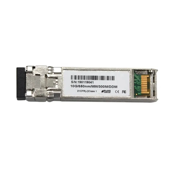
When a long-distance module transmits signals over relatively short distances—or when the receiver is too close to the transmitter—the intense optical signal may directly saturate the receiver's optical detector. Optical Modules (also known as Optical Transceivers) are critical components in fiber optic communication systems. As the core optoelectronic devices operating at the Physical Layer of the OSI model, their primary function is to perform electro-optical and photo-electric conversion during signal. As an essential component of optical fiber communication, optical modules are optoelectronic devices that facilitate the conversion between optical and electrical signals during the transmission process. This is not an arbitrary adjustment but a necessary measure, carefully implemented based on signal transmission principles, device specifications, and practical. Optical Signal Attenuation is the single greatest factor limiting the distance and performance of your network. Understanding it is crucial for anyone involved in data centers, telecommunications, or enterprise networking. This guide will demystify signal loss, explore its causes, and show you how. In the field of optical fiber communication, the attenuation operation of long-distance modules is one of the key links to ensure the stable operation of the communication system. This operation is not carried out arbitrarily, but is a necessary measure after comprehensive consideration of many.
[PDF]
IEC 60793-1-40:2024 establishes uniform requirements for measuring the attenuation of optical fibre, thereby assisting in the inspection of fibres and cables for commercial purposes. Four methods are described for measuring attenuation, one being that for modelling spectral. The Fiber Optic Association, Inc. (FOA) was founded in 1995 to help develop the workforce to build the fiber optic networks to support a rapid expansion in communications and the Internet. The charter of the FOA was to promote professionalism in fiber optics through education, certification, and. This Chapter is devoted to the description of the optical cable installation methods. Each type of optical fibre cable has a specific strain limit and special care and arrangements may be needed to ensure successful installation without exceeding it. Damage caused by overloading during installation. The International Electrotechnical Commission (IEC) is the leading global organization that prepares and publishes International Standards for all electrical, electronic and related technologies. The technical content of IEC publications is kept under constant review by the IEC. 65x series of recommendations are especially significant for professionals in the field. In this article, we delve into these. 4. FO-VC2 JOINT USE - VERICAL MIDSPAN CLEARANCES 48. FO-GB GROUNDING AND BONDING 49.
[PDF]