Abstract: Detecting partial discharges in cable joints is critical for timely defect identification and reliable transmission system operation. The electric field distribution of the optical fiber-implanted cable joint was simulated, followed by electrical performance tests, demonstrating that optical fiber implantation had a negligible effect on the electrical properties of the cable joint. A platform utilizing Mach–Zehnder–Sagnac. The results show that the average sensitivity of the sensor in the 10 kHz–80 kHz range is 71. 0 dB higher than that of the piezoelectric transducer, with a maximum signal-to-noise ratio of 65. To improve the long-term reliability and sensitivity of the sensing system, a novel method for cable joint monitoring based on implanting optical fibers. However, there is an industry gap in the literature about the highly sensitive fiber optic-based PD solution based on the acoustic emission principle. This paper aims to fill such an industry gap. In this paper, the fiber optic-based PD sensing (OptiFender) technology is applied to monitor the PD.
[PDF]

Discover the key differences between optical fiber cables and copper cables. OPTRAL analyzes the advantages and disadvantages to enhance connectivity. Optical and copper interconnection technologies represent two distinct approaches to data transmission, each with its own advantages and limitations. While fiber optics dominate in performance, copper retains its technical and economic justification. But how do you decide which one is best suited for your needs? This article delves into the technical comparison between copper and fiber optic cables. When it comes to modern data transmission, Fiber Optic cables and Copper Cables play pivotal roles in ensuring seamless connectivity. What Are Fiber Optic Cables? Fiber Optic cables function by transmitting data in the form of light pulses through optically pure glass fibers. These fibers are. “Fiber offers multiple technical advantages, including exceptional bandwidth, low attenuation and distortion over long distances, reduced bulk, as well as isolation from electromagnetic interference (EMI) and electrostatic discharge (ESD). ” Let's explore the characteristics, advantages, and. The two core material technologies used in almost all cables are fiber optic, and copper wiring. Whether you're looking at an HDMI cable, a USB cable, Ethernet patch cable, or any other kind of network of data transmission cabling, they are all built using copper or fiber optic internal wiring.
[PDF]
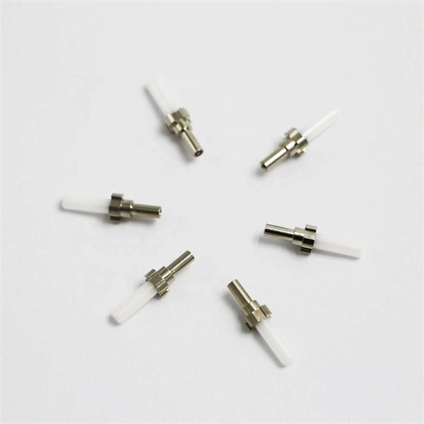
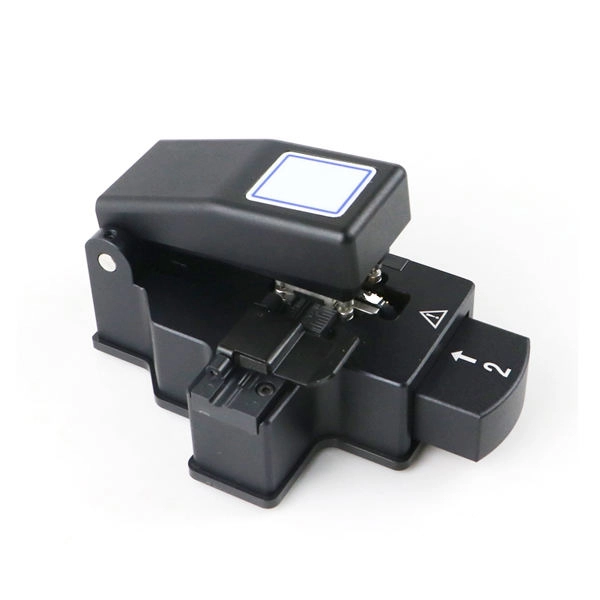
We terminate fiber optic cable two ways - with connectors that can mate two fibers to create a temporary joint and/or connect the fiber to a piece of network gear or with splices which create a permanent joint between the two fibers. Proper connection of fiber optic cables is essential to harness these benefits fully, as even minor errors can lead to significant performance issues like signal loss. These terminations must be of the right style, installed in a. Running fiber internally involves extending this high-speed link from the service entry point to a centralized location, such as a dedicated media closet or network rack. This DIY effort is undertaken to maximize performance, improve aesthetics, or relocate the Optical Network Terminal (ONT) to a. In this video, we'll guide you through preparing and terminating fiber optic cables using SimplyFiber products, known for their high quality, ease of use, and reliability. more Audio tracks for some languages were automatically generated. Two types of splices are used in fiber optic cabling one is Mechanical the other is Fusion. Whether you're installing a new network, expanding an existing one, or. But here's the thing: how you connect fiber optic cable really matters. A shaky connection means weaker signals, dropped streaming, or slow uploads. Get the hookup right, and you'll enjoy streaming, gaming, and video calls without interruptions.
[PDF]
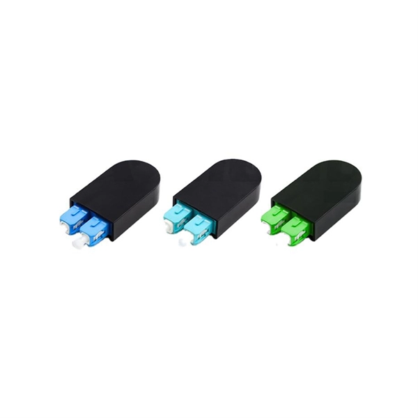
Get the wrong connector type, the wrong polish, or skip proper fusion splicing technique—and you're looking at elevated signal loss, increased back reflection, and a field termination that fails certification. Once you nail the logic chain— raw fiber → protected cable → spliced pigtail interfaces → flexible patching —you control loss budgets, installation time, and maintenance risk. Key takeaway: Treat the four items like a relay team. Each runs a specific leg so your network hits performance targets. In the intricate ecosystem of fiber optic networks, two components play a critical role in ensuring seamless connectivity: patch cords and pigtails. While both are essential for linking fibers to devices or other cables, they serve distinct purposes and are designed for specific scenarios. Executive Summary: A fiber optic pigtail is one of the most commonly specified yet least understood components in structured cabling. Despite their widespread use and numerous advantages, there are some circumstances in which they might not be the ideal option. A fiber optic pigtail is very practical for on-site terminations where fusion or mechanical splicers are used. Preterminated connectors offer several advantages over. Today, I'll show you how to pick the right patch cord or pigtail — step by step. A Fiber Patch cord connects two devices. You plug it into a switch, router, or patch panel. It's ready to use out of the box. A pigtail is for splicing.
[PDF]
Fiber optic "cable" refers to the complete assembly of fibers, other internal parts like buffer tubes, ripcords, stiffeners, strength members all included inside an outer protective covering called the jacket. Cable provides protection for the optical fiber or fibers within it appropriate for the environment in which it is installed. You will also learn how different aspects of the product can affect budget and design. ■ The Five Key Parts of a Fiber Optic Cable A fiber optic cable. A fiber optic cable consists of five basic components: the core, the cladding, the coating, the strengthening fibers, and the cable jacket. When searching for a fiber optic cable, we need to pay attention not only to the connectors, such as SC to ST fiber cable, LC to SC fiber patch cable, or SC to. A TOSLINK optical fiber cable with a clear jacket. These cables are used mainly for digital audio connections between devices. This advanced cabling solution allows fast, secure data transfer and telecom over long distances. Understanding the components within a fiber optic cable enables. While fiber optic cable itself is cheaper than an equivalent length of copper cable, fiber optic cable connectors and the equipment needed to install them have typically been more expensive than their copper counterparts.
[PDF]
Use this worksheet to input values for all variables that will impact your system's performance. After entering your values, please ensure you click the 'Calculate Link Loss' button at the bottom of the page to generate your total link loss. Add connectors, splices, bends, and safety margin easily. See results instantly above the form, then adjust values. Choose a mode, then enter values and optional losses. All calculations use base-10 logarithms. mW must be greater than zero. Used only in measured attenuation mode. Length is needed. The power budget refers to the amount of fiber optic cable plant loss that a datalink (transmitter to receiver) can tolerate in order to operate properly. Sometimes the power budget has both a minimum and maximum value, which means it needs at least a minimum value of loss so that it does not. To detect whether the link runs properly, the following calculation should be performed. It is often the case to calculate the maximum signal loss across a given fiber link during optical cable installation. First, you should be aware of the fiber loss formula: The Total Link Loss = Cable. Therefore, it is very important to calculate the fiber loss and take appropriate steps. In order to get the most reliable results, an Optical Time Domain Reflectometer (OTDR) trace of the actual fiber connection should be completed. This will provide you with the real.
[PDF]
Q: How far can multimode fiber go? A: The transmission distance of multimode fiber depends on the fiber type and data rate. OM3 and OM4 multimode fibers typically support up to 300m and 400m, respectively, for 10G Ethernet. At lower data rates, such as 1G Ethernet, multimode fiber. Multimode fiber optic cables are designed to carry multiple light modes simultaneously, each taking a different path or mode through the fiber. This characteristic makes MMF ideal for high-bandwidth applications over relatively short distances. Common applications include Local Area Networks. Fiber optic cable transmission distance is determined by two primary physical factors that affect signal quality as light travels through the fiber medium. The greater the distance, the greater. A: Single mode fiber can typically transmit up to 160 km, and with dispersion compensation, it can exceed 200 km. For most enterprise or data center applications using multimode fiber, the practical limit sits between 300 m and 550 m. However, the dispersion-compensating fibers can support more than 200 kilometers. How. For instance, without amplifiers, single-mode fiber can reach 50-60 miles and can support data rates of 1 Gbps or 10 Gbps. With amplifiers, such as Erbium-doped fiber amplifiers (EDFAs), the distance can be extended to 600 miles or more, and even further with additional amplifiers for long-haul.
[PDF]
Fiber optic cables are also more secure, as they are harder to tap or hack. Fiber and copper cable repair both require trained splicers, but the tools, techniques, and failure modes are completely different. Sending a fiber splicer to repair a copper cable - or vice versa - wastes time and risks making the damage worse. Here is what you need to know before you call for. Well-made fiber optic cables are very tough, making them great choices for homeowners who would like to limit weather-related internet outages as much as possible. The comparatively high durability of fiber optic cables comes from a series of factors, including: The quality of the glass cables, of. Copper and fiber optic cables each offer distinct advantages and disadvantages that can impact performance, cost, and long-term efficiency. But how do you decide which one is best suited for your needs? This article delves into the technical comparison between copper and fiber optic cables. Fiber optic cables are typically damaged in one of two ways: A premade fiber optic cable suffers connector damage when too much pull-force is applied during installation. This can occur on long cable runs through tight conduit or duct, and also if the cable becomes caught or snagged.
[PDF]
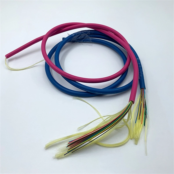
Microducts are pipes used for the installation of fiber optic cables, can be produced in different colors and have high crush resistance. Available Universal Routing Kits 24F or 36F enable quick separation of fibers into 2 x 12 or 3 x 12 fiber sets with a furcation tube that protects the fibers from sharp edges in closures and cassettes. These universal routing kits provide the ultimate solution for those users who want to route. The kink-resistant buffer tube contains multiple 12-fiber sets of color-coded fibers. Each set within the buffer tube is grouped using dual color-coded binder threads. The dry-blocked core is made up of SZ-stranded buffer tubes around a central strength member. The low-friction, high-strength. Loose tube cables to install in microducts (Blowing). Available in high density of fibers. Can be directly terminated. Loose tube cables for indoor and outdoor. Loose tube cables with flexible tubes for indoor. MLT Microduct optical fiber cables are robust solutions for micro duct outside plant installations. They have stranded micro loose tubes and water blocking gel, they ensure durability and reliability. The addition of a thermoplastic dual jacket in certain models enhances resilience and ease of. Prysmian's microduct cables offer a step forward in cable miniaturization by boasting world record fibre densities and cable diameters. EasyFiber® Microduct, have a thin outer jacket for fast and easy installation.
[PDF]
Drawing on IEC standards and industry research data, it outlines the coverage of mainstream outdoor fiber optic cable types, selection criteria, and best practices for installation, providing a systematic reference for outdoor fiber optic cable deployment. This document serves as a guide for outdoor fiber optic cable selection and installation for professionals in the telecommunications industry. Fiber optic cables for outdoor applications are engineered to withstand the more demanding conditions seen outside, from environmental extremes to mechanical forces. These are the outdoor fiber optic cables you see strung along telephone poles (aerial), installed inside an underground duct, or even. Outdoor fiber optic cables transport data and communications signals over long distances while enduring extreme environments. Whether you're linking buildings, running broadband in rural areas, or building 5G infrastructure, the right cable matters. It affects performance, maintenance, cost, and reliability. Our team will make sure the configuration is tailored to your needs and will provide a detailed quote. Email us using the Request a Quote below, or. hing, conduit and temp rature variations. The Outside Plant cable. These cables are thoroughly tested designed for installation in pathways that are subjected to wide product line offers 6 and 12 fibers per and verified to Telcordia GR 20 a loose tube cables and hybrid design o ts to specific.
[PDF]
The modern world relies heavily on electrical and communication cables that must be managed and supported across vast distances in commercial and industrial settings. A cable tray is an organized support structure designed to secure and route these insulated electrical cables. In the electrical wiring of buildings, a cable tray system is used to support insulated electrical cables used for power distribution, control, and communication. Cable trays are used as an alternative to open wiring or electrical conduit systems, and are commonly used for cable management in. Whether you're planning a new office setup or upgrading your existing network, the choice of a cable tray system plays a significant role in ensuring the reliability and scalability of your structured cabling solution. It acts as a. en completely installed, without damage either to conductors or structural system use maintain spacing or to keep cables in place when the tray is ect the minimum bend ra-dius for cables as they exit the bottom of the cable tray. A rung spacing of 6 to 9 inches (150 to 230 mm) is preferable when. Explore various cable tray types and sizes for electrical installations. Learn about ladder, perforated, solid-bottom, wire mesh, and channel trays in this complete guide. What is Cable Tray Systems? 1.
[PDF]
View or download our complete Fiber Optic Cable Catalogue with detailed specifications, certifications, and technical information. RHINO Cable is one of the leading Power and Communication cables suppliers in Ethiopia with more than 10 years of experience. Explore our comprehensive range of high-quality electrical, telecom, and fiber optic cables. Our product catalogue features detailed specifications and images to help you find the right solution for your project needs. BMET Energy Telecom Industry and Trade PLC” is the biggest capacity electrical. The Ethiopia Fiber Optic Cable Market is poised for steady growth rate improvements from 2025 to 2029. 41% in 2025, the growth rate steadily ascends to 16. Manufacturing excellence with 700,000,000. General Symmetric cable pairs Land coaxial cable pairs Submarine cables Free space optical systems G. 649 Optical fibre cables G. 659 Characteristics of optical components and subsystems Characteristics of optical systems G. 679. In Ethiopia, Huawei unveiled its brand-new OptiXtremeTM 400G DR4 series of fibre optic cables. The cables come in a range of lengths and configurations, and they can transport data at rates of up to 400 Gbps. In. Tailor every aspect of your fiber optic solutions — from cable type, connector style, and jacket material to branding, labeling, and packaging. We're here to support your fiber network needs.
[PDF]
Naficon Liitin Oy, the parent company based out of Finland is one of the most trusted suppliers for telecom, data centers and utility across Northern Europe. Naficon Fiber Optic Manufacturing LLC in Dubai, UAE serves as a major Manufacturing and Supply Centre in the Middle East. We are a leading manufacturer of Optic Fiber Cables in the United Arab Emirates. With advanced technology, strict quality standards. The United Arab Emirates (UAE) is a thriving hub for fiber optic cable manufacturing, offering advanced solutions to meet the region's growing demand for high-speed internet and reliable telecommunications infrastructure. Here, we explore some of the leading fiber optic cable manufacturers in the. The best connection for your application. New web catalogue, with productfinder and new search function. Search the complete range of products of Lapp Group. This website uses cookies and similar technologies (hereinafter "cookies"). Providing a happier, richer future through providing solutions for copper and optical communication for the past 20 Years. Established to meet the evolving needs of the telecommunication infrastructure network, AFOC focuses on delivering innovative, customized, and competitive optic fiber cable products. NAFICON is a fiber industry expert with over 30 years of manufacturing legacy.
[PDF]
Need some clarification about NEC 770. 47 (B), it says that the direct buried conductive fiber optic cable shall be 12 in (300 mm) away from the power cables. Separating high-voltage power cables from low-voltage communication cables is a fundamental requirement in any electrical installation. This practice is mandatory for two distinct reasons: ensuring the safety of the structure and its occupants, and preserving the integrity of sensitive data. Maintaining proper separation between power, data, and limited energy cabling is foundational to system performance, safety, and code compliance. Separation isn't just an EMI precaution — it protects signaling, reduces rework, and ensures pathways meet inspection expectations across risers. TECHNICAL GUIDELINE July 30, 2020 TG030 Rev. 4 Pathway Separation Between Telecommunication Cables and Power Cables Communications cables are, by design or necessity, often installed in close proximity and/or in the same pathway as power service cables. The electrical energy of the power cables can. This standard titled “Commercial Building Standard for Telecommunications Pathways and Spaces” is a joint publication of ANSI/TIA/EIA. Its current version (ANSI/TIA/EIA/-569-B) was published in October 1, 2004 and describes EMI aspects in Article 10. ca with numerous contributions by others. "UTP Separation Guidelines From EMI Sources". The values are the same as the cabling pathways standard, EIA-569, table 4.
[PDF]
Optical Fiber Cables Price in Bolivia - 2025 - Charts and Tables - IndexBox. What's the difference? Get instant access to more than 2 million reports, dashboards, and datasets on the IndexBox Platform. The average optical fiber cables import price stood at $3,850 per ton in 2023, reducing by -8. 1%. Buyers typically pay for fiber optic cable by length, fiber type, and installation complexity. Main cost drivers include cable grade (indoor vs outdoor, armoured), distance, and labor for trenching, splicing, and termination. This guide presents ranges in USD and practical price estimates to help.
[PDF]