Positive busbars, which collect all positive connections. Key Steps: When wiring a pair of 12V busbars, connect the positive terminal of each load to a stud on the positive busbar and their negative terminal to a stud on the negative busbar. 5' above batteries on inside of cockpit combing below decks. Install one new positive bus bar beside the negative one separated by about two inches 3. Positive and negative busbars are physically identical apart from the red/black colours used by some manufacturers to visually differentiate between. A Complete Guide to Battery Terminal Connector Types The store will not work correctly in the case when cookies are disabled. JavaScript seems to be disabled in your browser. For the best experience on our site, be sure to turn on Javascript in your browser. Skip to Content Blog Sign In Create an. This image illustrates a standard car battery with top post terminals and labeled connectors for the positive (+) and negative (–) ends, emphasizing safe and correct installation. A battery terminal connector is a fitting or clamp that attaches to a battery's terminal to connect a cable. In other. Both positive and negative terminals are the soul of the electrical system of the car, allowing the engine to start while keeping other components running. The catch? Mix-up or loose connection can cause electrical failure, drained batteries, and damage to wiring. This blog guides you how the two.
[PDF]
Different solar panels will have information on the sticker on the back showing how to test. (1) Using a voltage meter, locate the open-circuit voltage (Voc) on the specifications label on the back of your solar panel. Write it down for late. Different solar panels will have information on the sticker on the back showing how to test. (1) Using a voltage meter, locate the open-circuit voltage (Voc) on the specifications label on the back of your solar panel. Write it down for later use. To measure the voltage of a DC circuit, you should prepare your multimeter by plugging the black probe. The short circuit current (Isc) on a circuit panel is located on the specifications label on the back of the panel. Record this number for later use. To prepare your multimeter to measure amps, move the red probe to the amperage terminal and set your multimeter to the amp setting (A). If your multimeter is not automatic-ranging, be sure to choose t. You can also measure the voltage of a photovoltaic panel (PV Current) by connecting it to a charge controller. It's possible to use a multimeter to determine how much current your solar panel is outputting, but you'll need an extra piece of equipment first. 1. Solar charge controller 2. Battery Plug the solar charge controller into the battery. Con.
[PDF]
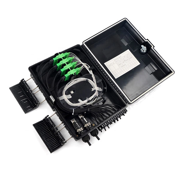
Fiber testing is the process of verifying the performance of optical fiber cabling. This process includes a range of tests and measurements such as insertion loss, optical return loss, and fiber length. It encompass.
[PDF]
IEC 61537:2023 specifies requirements and tests for cable tray systems and cable ladder systems intended for the support and accommodation of cables and possibly other electrical equipment in electrical and/or communication systems installations. Covers construction and test requirements for. The International Electrotechnical Commission (IEC) is the leading global organization that prepares and publishes International Standards for all electrical, electronic and related technologies. The technical content of IEC publications is kept under constant review by the IEC. Please make sure. association representing the major electrical equipment manufac-turers in the U. The Cable Tray ng standards, performance standards, test standards and application in this document have been tested extens ompetent professional en completely installed, without damage either to conductors or. us-trations without notice. All illustrations, descriptions and technical information included in this document are provided as indications and can cable trays are equivalent. For proper installation, design, and maintenance, adherence to international standards is essential. One of the most recognized frameworks globally is the IEC standard for.
[PDF]
Headquartered in Singapore, NEXUSTEST is a global supplier of high-end test equipment for the optical and semiconductor markets. We design and manufacture advanced test instruments and systems for high-speed optical modules, laser diodes, Silicon Photonics wafers, and Co-Packaged. Optical module chips are core components in optical communication systems, playing a critical role. They are primarily used to convert electrical signals into optical signals and vice versa, enabling high-speed data transmission. Optical module chips are widely used in data centers, communication. site configuration. The exponential growth of computational centers, fueled by this technological progress, is driving a revolution. In this context, the demand for 800G and 1. 6T optical modules has. Accurate, flexible, fast testing of photonic integrated circuits (PIC) with traceable results. Complete PIC testing platform for precise and repeatable optical alignment and electrical probing. Preparation, automated execution (navigation, alignment, instrument control) and data management. Photonic integrated circuits (PICs) are a key enabler driving advances in communications, optical computing, aerospace, defense and medical applications. Before manufacturers ship any optical module, engineers must verify its performance, stability, and compatibility. Without systematic optical module testing, it becomes difficult to identify whether transmission.
[PDF]
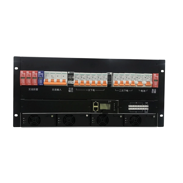
Voltage/BIL: 35 kV class, typical BIL 170 kV. Short-circuit: 25–40 kA short-time withstand common; confirm with system fault study. Continuous current: 1250–3150+ A bus and feeder options. Standards: IEC 62271-200; internal arc testing per IEC/TR 61641 if specified. The Insulation levels for Distribution, Class 1 and Class 2 transformers shall be selected from this table for both the high-voltage and low-voltage windings. All test levels are line to ground. The applied test levels are not applicable to wye-connected windings unless they have been specified to. PURPOSE: To provide general construction requirements for representative wood pole structures and assemblies for 34. 5 through 69 kV transmission lines. 2-1. Most distribution voltages are between 4 and 35 kV. In this article, unless otherwise specified, voltages are given as line-to-line voltages; this follows normal industry practice, but it is sometimes a source of confusion. A voltage class is. This article is for manufacturing, testing of non-segregated Bus Bars and Bus Ducts rated 600 V to 35 kV as per international standard ANSI C37. Air insulation with generous. Rated maximum voltage, kV BIL, kV Manufacturing Date: MM/YYYY Rated continuous current, A Rated load interrupting rating, A Momentary current rating, kA asym. Close & latch rating, kA asym. Liquid dielectric volume (gallons) – Liquid-Filled Units Only SF6 Weight, Pressure – SF6.
[PDF]
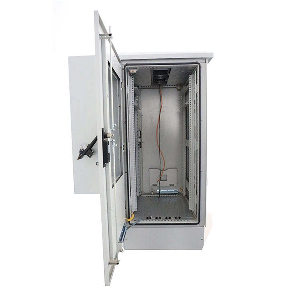
In this step-by-step tutorial, we'll cover: ✅ Tools you need ✅ Safety precautions ✅ Mounting the box ✅ Wiring tips ✅ Final checks Perfect for beginners, DIYers, and electricians who want a clear installation guide. more Learn how to properly install an electrical box . A distribution box is the heart of any electrical system. It takes the incoming power and safely distributes it to different circuits throughout your building. Whether in a home or an industrial facility, this box keeps your electrical setup organized, functional, and efficient. However, the key to. Muna 2022, maguta mazhinji akatanga kutangazve basa nekugadzira mushure mekusangana nedambudziko redenda. Sekureva kwaFu Linghui, mutauriri weNational Bureau of Statistics, huwandu hwehupfumi hweChina hwakasvika 114 trillion yuan muna 2021, pachinzvimbo chechipiri pasi rose. We will focus on the critical parts of the system, from basic components to step-by-step assembly procedures. Whether you are looking to. In just a few steps you will find the wiring and assembly plan, including complete documentation in accordance with standards. This is the design philosophy which the browser-based distribution board configurator from Eaton is based on. It serves as a central hub for distributing electricity throughout a building, ensuring that power is delivered safely and efficiently to all the required locations.
[PDF]