This AutoCAD DWG file includes a complete Single Line Diagram (SLD) of a Distribution Board, showing circuit breakers, wiring connections, and load distribution for lighting, power, and mechanical systems. An electrical panel box, also known as a breaker box or a distribution board, is a crucial component of any electrical system. It serves as a central hub for distributing electricity throughout a building, ensuring that power is delivered safely and efficiently to all the required locations. And all the switching and protective devices are installed in the. A distribution box is a key part of electrical systems in buildings. Inside, you'll find parts like circuit breakers and fuses that protect the system from problems like overloads and short circuits. Today, electrical systems are essential for homes and industries. Electrical Distribution board is used for controlling of utilization of power in the end point like as lighting circuit, power circuit and other equipment like as TV, fridge and airconditioning. The incomer supply is received from distribution panel. In this board, balance load is distributed as.
[PDF]
In this video, we'll walk you through the process of wiring a home distribution box with a detailed connection diagram. Understanding the cable TV house wiring diagram can be helpful when troubleshooting connection issues or setting up new TV sets in your home. Whether you're an electrician or a DIY enthusiast, this guide will help you understand the basics of home electrical distribution. more Welcome to our channel! In this video. This course was adapted from the Department of Energy, Publication No. DOE-HDBK-1011/2-92, “Electrical Science”, Module 15, which is in the public domain. Gussow, Milton, Schaum's Outline Series. Distribution board is a safe system designed for house or building that included protective devices, isolator switches, circuit breaker and fuses to safely connect the cables and wires to the sub circuits and final sub circuits including their associated Live (Phase) Neutral and Earth conductors. Once this is identified, the wiring diagram should be drawn up, showing the main power line coming from the utility source and then branching off to the various branch circuits. This diagram should also indicate the type of circuit breaker used on each branch circuit. In addition to the main power.
[PDF]
Simple 3-phase distribution board wiring diagram for home use, showing safe connection of power supply, breakers, neutral, and earth for residential electrical systems. Hey, in this article we are going to see the Three (3) Phase Distribution Board Wiring Diagram and Connection Procedure. The three-phase distribution board is used to distribute power to the three-phase loads and circuits such as three-phase motors, three-phase machinery, three-phase to. In a newly constructed residential area, a 10kV power line is introduced into the substation. After stepping down the voltage through the transformer's low-voltage side (0. The following is a detailed introduction about it: - **First-level Distribution. Utilities may have some control over and access to the energy stored in electric vehicles attached to the grid. ndards and conformity assessment activities in the United States. ANSI facilitates and promotes voluntary consensus standar rty or economic loss due to fire, electrical and related hazards. They deliver information and knowledge through more than 300 consensus codes and nspection to protect people.
[PDF]

The total interruption time for a modern high-voltage SF6 circuit breaker is typically between 40 to 60 milliseconds on a 50Hz grid, or 2 to 3 cycles. This is the total time from the trip signal to the final arc extinction, a critical parameter for grid safety. While knowing the total time is a. When a SF6 circuit breaker (CB) hits its critical low pressure, its fault interrupting capability can be compromised. Most TOs protect against this by either auto-opening the CB prior to reaching the critical low-pressure level or by blocking the CB from tripping (when it reaches the critical. The protected zone is defined and limited by different things depending on the protection function. Definite time delay means that the protection operate time dose not change or depend on the fault type or the fault current magnitude. Instead of oil, air, or a vacuum, a sulfur hexafluoride circuit breaker uses sulfur hexafluoride (SF 6) gas to cool and quench the. Page 1 Content Instruction Manual circuit- breaker GL317 With spring operating mechanisms FK3- 4 Administrator First issue Compiled by Approved by 19- 11- 2012 J. Texier Imagination at work Grid Solutions 04- 2017 D1736EN/03 GE Information 1/10. Page 2 Content Instruction Manual This. A comparison of the time it takes protective devices to operate when certain levels of normal or abnormal current pass through them. LV circuit breaker ratings.
[PDF]
In Canadian service entrance panelboards the main switch or circuit breaker is located in a service box, a section of the enclosure separated from the rest of the panelboard, so that when the main switch or breaker is switched off no live parts are exposed when servicing the branch circuits.OverviewA distribution board (also known as panelboard, circuit breaker panel, breaker panel, electric panel, fuse box or DB box) is a component of an that divides an electrical power feed into subsidiary. North American distribution boards are generally housed in enclosures, with the positioned in two columns operable from the front. Some panelboards are provided with a door covering th. This picture shows the interior of a typical distribution panel in the United Kingdom. The three incoming phase wires connect to the busbars via a main switch in the centre of the panel. On each side of the panel are two.
[PDF]
Electric recommends these steps to restore power safely when your circuit breaker trips. Turn off and unplug devices on the affected circuit. Locate your electrical panel and identify the tripped breaker. Reset the breaker by switching it fully off, then back on. To effectively troubleshoot a tripping breaker, you should begin by identifying potential causes, such as overloaded circuits, short circuits, or faulty wiring. With a little investigation, you can often pinpoint the issue before considering a call to a professional. One of the most common and easily fixable problems is a tripped. Mr. Plug in devices one at a time. A tripped circuit breaker is usually a sign that there's too much electrical load on the circuit, or there's a short circuit somewhere in the system. Understanding how to troubleshoot a tripped circuit breaker is essential for any homeowner or DIY enthusiast, as it can help you safely restore. A circuit breaker is an automatic electrical safety device designed to protect your home's wiring and connected appliances from damage caused by an overcurrent condition. Once a circuit breaker trips, you cannot use any switches, outlets, or any fixture it serves.
[PDF]
If your breaker box lacks a main breaker 3, look for a split-bus panel 4 design with up to six main disconnects at the top section, or check outside for a separate main disconnect near your meter. In emergencies, you may need to shut off multiple breakers. Older homes often have panels that predate modern requirements, and in some cases, subpanels or unique building designs eliminate the need for a main breaker. An electrical panel, often called a breaker box or distribution board, is a critical component of a home's electrical system. It serves as. The distribution box (DB box) helps safely and efficiently distribute electrical power. Today, electrical systems are essential for homes and industries. What size distribution box do you need for a house? How do you know which circuit breaker to use? Can you add more breakers later? Why do you need GFCI or AFCI breakers? Choosing the right size and setup for your distribution box keeps your electrical system safe and working well. Also called a distribution board, panel board, breaker panel, or electric panel, it is the central hub in an electrical system that divides incoming power into various subsidiary circuits. I contend that in order to disconnect the power to the distribution panel, you have to open both the normal and generator circuit breakers (cannot be disconnected by a single breaker). The main disconnect is usually 200 amps but can sometimes be as low as 100 amps.
[PDF]
This document describes how transformer inrush current can cause nuisance tripping of standard trip circuit breakers during start up or application of power. Recommendations for selecting a high inrush compensated circuit breaker are provided. Protective devices like circuit breakers and fuses are essential, especially for transformers operating over 1,000V, to ensure safe operation and compliance with code requirements. A transformer can generate an almost infinite current. Our telecom client has an inverter with an internal 40kVA, 480V delta to 120/208V wye transformer supplying a bypass circuit for the inverter. The only time the transformer has a load on it is when the inverter is in bypass. Normally DC power is converted to AC power to feed the critical loads. From transformer secondary currents with lower loads that survive without a breaker trip, I see an open time of about 30ms. Feeding a 45kVA dry, three-phase transformer 480V to 160V AC, 55FLA, for generator. When a transformer is energized, it draws a large current for a few cycles to establish the eletromagnetic field. Inrush can vary depending on where the sine wave is during initial energization and how. The 13 loads on the first circuit breaker panel would reach a total of 70kVA/102A, the 12 loads on the second circuit breaker panel bring it to 41kVA/96A. Yes, both of your options would be.
[PDF]
Square D by Schneider Electric offers a unique replacement kit designed to adapt to all brands, different use case scenarios and load type devices such as Load Centers and CSEDs. This kit consists of tw.
[PDF]
In today's step-by-step guide, we will demonstrate how to select the right size panelboard (whether it's a load center, distribution board, or circuit breaker panel) according to NEC and IEC standards, wit.
[PDF]
Circuit breakers are specialized switches designed to detect faults and stop the flow of electricity in high-stakes environments. In substations, they are configured to handle higher voltages and currents than those of household breakers. They play a pivotal role in protecting the. Substation circuit breakers are vital components within electrical substations, tasked with protecting the entire system by detecting and isolating electrical faults. This device serves as a guardian, protecting the substation and its equipment from potential electrical hazards. It is responsible for disconnecting faulty parts of the grid while keeping the rest of the system running smoothly. In a substation, the circuit breaker is the piece of equipment that matters most.
[PDF]
Roadside Telecommunications (RS-TC) Fiber Optic Cable Installation Adjusted Capital Cost Scatter Plot The data used to produce this cost plot are sourced from the ITS Sample Unit Costs Database. These cost data are obtained directly from a variety of sources. Buying fiber optic installation services involves several cost components, with total price influenced by length, location, and access. The main cost drivers include trenching or aerial deployment, materials, labor hours, and any required permits. This guide presents typical price ranges in USD to. Costs to run fiber optic cable vary by distance, trenching needs, cable type and labor rates. This guide outlines typical price ranges and what drives the total cost for U S buyers. Commercial building installations with 100-200 network drops generally range from $15,000 to $30,000. You should account for permit. Typically, per drop fiber cabling prices range from $250 – $1000 per drop depending on the type of fiber (OM2, OM3, OM4, or OM5), multi or single mode, PVC or plenum, average drop length, and also the number of fibers in each cable. Unit cost descriptions have not been.
[PDF]
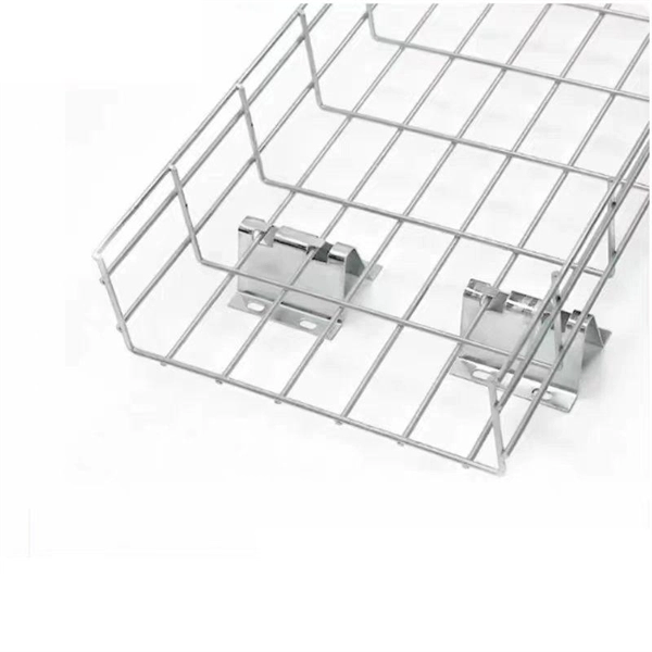
Download a comprehensive set of Cable Tray Installation CAD Blocks in DWG format, ideal for electrical engineers, MEP designers, and industrial layout planners. This article shares simple ways to plan your cable trays and wiring. We want to help electrical engineers, technicians, and anyone working with electrical setups build safe and good systems. This collection includes installation details for ladder trays, perforated trays, solid-bottom trays, and wire mesh trays, along with. This guide provides step-by-step instructions on installing a cable tray on a wall, covering different types of cable trays, tools needed, and safety tips. The Ladder Tray features light, rugged, tubular steel construction. It is designed for. In industrial settings, electrical and instrumentation (E&I) cable trays or bridge racks play a critical role in organizing and supporting power, control, and signal cables across facilities. An effective layout ensures safety, minimizes interference, reduces maintenance time, and keeps the overall. ALL TO BE CLEANED WITH A COMMERCIALLY AVAILABLE CLEANSER PRIOR TO ALL MARKERS AFFIXED PRIOR TO INSTALLATION OF ANY CABLE. BONDING JUMPER SHALL BE INSTALLED FOR ELECTRICAL CONTINUITY ACROSS ALL DETAIL AT INTERFACES AND/OR CONDUIT BUSHINGS SHALL INSTALLED FCR ENTRY OF CABLES.
[PDF]

Welcome to our channel! In this video, we'll walk you through the process of wiring a home distribution box with a detailed connection diagram. more Welcome to our. Understanding the wiring diagram of an electrical panel box is essential for electricians and homeowners alike, as it allows them to troubleshoot any electrical issues, carry out repairs, or make additions to the system. What is Distribution Board? Distribution board. Hey, in this article we are going to see the Single Phase Distribution Box Wiring Diagram and Connection Procedure. A distribution board or distribution box is where the main power supply is distributed to multiple loads. And all the switching and protective devices are installed in the. That's why having a clear, detailed diagram of your home's distribution board wiring is essential. The diagram. Product Overview Renogy PMS1280 Smart Distribution Box is a centralized direct current (DC) power control hub specially designed for off-grid recreational vehicles, yachts, and motorhomes. The distribution box provides 12 circuit channels for load control as well as voltage and current detection.
[PDF]
In telecommunications, an eye pattern, also known as an eye diagram, is an oscilloscope display in which a digital signal from a receiver is repetitively sampled and applied to the vertical input (y-axis), while the data rate is used to trigger the horizontal sweep (x-axis). It is so called because, for several types of coding, the pattern looks like a series of eyes between a pair of rails. It is a too. CalculationThe first step of computing an eye pattern is normally to obtain the waveform being analyzed in a quantized form. This may be done by measuring an actual electrical system with an oscilloscope of sufficient bandwidth,. Each form of baseband modulation produces an eye pattern with a unique appearance. The eye pattern of a signal should consist of two clearly distinct levels with smooth tra. Many properties of a can be seen in the eye pattern. applied to a signal produces an additional level for each value of the signal, which is higher (for pre-emphasis) or lower (for de-emp.
[PDF]