Our CAD drawing files are available as . STP files for download. Discover Autodesk Revit's RVT format for our T&B cable tray BIM files. With its intuitive interface and robust features, Revit streamlines design, offering enhanced customization. Access and download T&B cable trays Revit files for free now! Find and download Intergraph Smart 3D CAD VUE files for. Our CAD drawing files are available as. Discover all CAD files of the "Cable trays" category from Supplier-Certified Catalogs ✅ SOLIDWORKS, Inventor, Creo, CATIA, Solid Edge, autoCAD, Revit and many more CAD software but also as STEP, STL, IGES, STL, DWG, DXF and more neutral CAD formats. can access every toolset, what can you do that you couldn't do before? Do you know that you can use AutoCAD MEP software to create cable tray, hanger, conduits pipe fitting, and MvParts that you can use in AutoCAD Plant 3D software? Getting started with the parametric parts can intimidate a new. Tray installation details for the location of a project's electrical wiring; in addition to blocks with different angles that allow the wiring circulation to be identified. Free CAD and BIM blocks library - content for AutoCAD, AutoCAD LT, Revit, Inventor, Fusion 360 and other 2D and 3D CAD applications by Autodesk. You can exchange useful blocks and symbols with other CAD and BIM users.
[PDF]

The Box Fill Calculator is an essential electrical installation tool that determines the maximum number of conductors, devices, and fittings that can be safely installed in electrical boxes according to National Electrical Code (NEC) standards. Plan devices by location with clear gang strategies and packing options built‑in. Enter outlets, switches, low‑voltage, fans, and junctions per space including spare allowance. Auto‑pack calculates 4‑, 3‑, 2‑gang mixes, minimizing wall clutter and box count. Instantly see totals per room and. Calculate electrical box fill capacity and ensure NEC compliance for proper wire management and electrical safety. Calculate electrical box fill per NEC 314. 16, including conductors, devices, clamps, and grounding. Ensure your installations are safe and code-compliant. 16 mandates these calculations to prevent overcrowding, which can. It takes the incoming power and safely distributes it to different circuits throughout your building. Whether in a home or an industrial facility, this box keeps your electrical setup organized, functional, and efficient. However, the key to a safe and reliable system lies in proper installation.
[PDF]
This calculator provides the calculation of the total frequency bandwidth used by a WDM system. Calculation Example: The total frequency bandwidth used by a WDM (Wavelength Division Multiplexing) system is calculated based on the number of channels, the channel spacing, and any guard. Calculate wavelength division multiplexer (WDM) system parameters including wavelength spacing, total bandwidth, spectral efficiency, system capacity, and frequency range. WDM allows multiple data channels at different wavelengths to be transmitted simultaneously over a single optical fiber. In fiber-optic communications, wavelength-division multiplexing (WDM) is a technology which multiplexes a number of optical carrier signals onto a single optical fiber by using different wavelengths (i., colors) of laser light. This technique enables bidirectional communications over a. Wavelength Division Multiplexing (WDM) is a technique in fiber-optic communication systems that enables multiple optical signals with different wavelengths to be combined, transmitted, and separated over a single optical fiber. To begin with, we assume that we have the element. Wavelength multiplexers and demultiplexers are needed in order to be able to use wavelength division multiplexing. The chapter begins with a quick historical account of the origin of optical communication and its exponential growth following the invention of erbium oped fiber amplifier (EDFA) leading to the widespread adoption of WDM.
[PDF]

The C-Channel & Steel Channel Calculator is a free engineering tool that instantly computes weight, bending moment, shear force, and deflection for standard or custom C-channels. We independently provide precision steel tools, calculators, and expert resources for steel, metalworking, construction, and industrial projects. Interactive calculator for American standard steel C channels. Select the channel depth and weight per unit length to obtain dimensions, cross-section area, moments of inertia, section modulus and radii of gyration according to ASTM A6/A6M. Use this steel C channel sizes calculator to quickly look. SkyCiv C Channel Load Capacity Calculator is a free tool designed to help you determine the strength and capacity of steel channel beams. It calculates the capacity of a channel and angle section based on the dimensions, span length. This tool calculates the properties of a U section (also called channel section or U-beam). Enter the shape dimensions h, b, t f and t w below. The calculated results will have the same units as your input. For full table with Static parameters Moment of Inertia and Elastic Section Modulus - rotate the screen! The standard method for specifying the dimensions of a American Standard Steel Channels is like C 5 x 9.
[PDF]
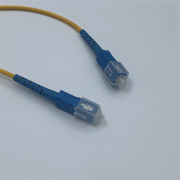
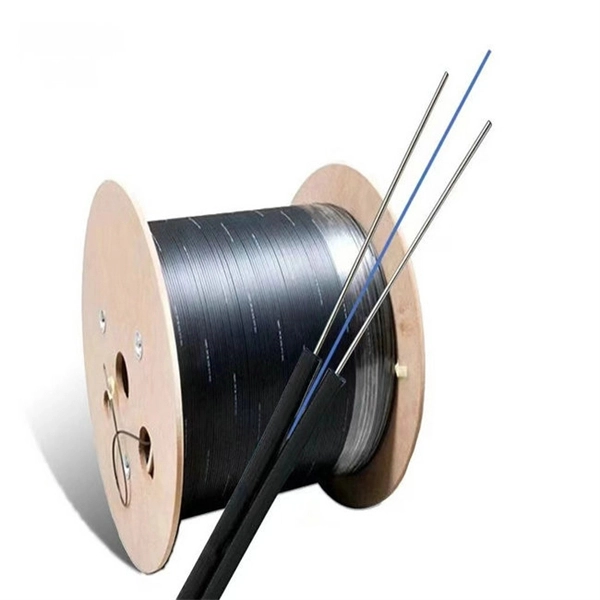
The normal recommendation for fiber optic cable is the minimum bend radius under tension during pulling is 20 times the diameter of the cable (d). This includes pulling tension, minimum bend radius or diameter and crush loads. Installers must understand these specifications and know how to install cables without. The correct bend radius calculation is a fundamental prerequisite for high-quality fiber optic installations and is decisive for long-term network performance and reliability. Why Use. Check safe bend radius, loop clearance, and slack for racks, risers, conduits, and storage coils before you route the fiber. The calculator uses conservative routing multipliers, then compares the actual bend radius against the cable family minimum so you can spot risky turns early. Configuration. Key Takeaway: Bend Radius is the minimum curve a cable can handle without damaging its internal structure or degrading the signal. Maintaining the integrity of your network requires more than just high-quality hardware; it demands precise installation. Cable bend radius is the critical threshold. Professional bend loss calculator for optical fibers. Analyze macrobending and microbending losses, determine critical bend radius, and optimize fiber routing for laser delivery systems and communication applications.
[PDF]
Use this Protection Relay Setting Calculator to calculate pickup current, time multiplier settings (TMS), operating time, coordination time interval (CTI), and plug setting multiplier (PSM) using fault current, CT ratio, and IEC 60255 curve parameters. of protective relays in terms of protecting high voltage lines. At the beginn ng of the article it is drawn up process to protect power lines. Consequently, it is shown the method of calculation for a particular power line a d performed the calculation for setting the distance protection. These calculations are critical in industrial. ve reliable and properly coordinated relay settings. Protection coordination refers to the systematic arrangement and interaction of protective devices within an electrical distribution network to ensure that faults are isolated in a controlled and orderly manner. The. With the help of these spreadsheets below, you can make your endless calculations much easier! Contact us for more information and download:.
[PDF]