SENKO Advanced Components provides precise, user-friendly, and application-focused fiber optic connectors, enabling network operators to achieve the performance and reliability needed to meet the world's unquenchable demand for data. Fibertronics, Inc. is in compliance with AS9100D and ITAR certifications, has been officially assessed by NSF-ISR. Our plenum rated (OFNP) assemblies meets NEC 770 compliance and standards. Custom cable assemblies are in compliance with EIA-455-171, FOTP-171, NECA-FOA-301, and IEC 61280-4-5 testing. Also, please take a look at the list of 48 fiber optic connector manufacturers and their company rankings. Here are the top-ranked fiber optic connector companies as of May, 2026: 1. Thermalogic Corporation, 2. What Is a Fiber Optic Connector? What Is a Fiber Optic. Molex completes acquisition of Teramount Ltd., a developer of detachable fiber-to-chip connectivity solutions. Learn More The addition of Smiths Interconnect positions Molex to drive innovation across markets where high reliability is critical and unifies a borderless platform for ruggedized. With 30 years of fiber optic experience and a continually expanding network of distributor partners and local rep firms, OPTIX America is a leading manufacturer of fiber optic products and solutions to the marketplace. Read the latest news from Hirose USA.
[PDF]
This paper deals with a framework to support the design optimization of an overhead line using methods related to the theory of the Constraint Satisfaction Problem. The object-oriented model of a transmission line has been described and then implemented into a. INTRODUCTION: Artificial intelligence is a product of high-end technological development since the 21st century, which has subverted people's traditional cognition in many aspects and greatly enriched and improved people's lives. Artificial intelligence has covered every aspect of life, and the. OVERLAY VS. 50. The Power Distribution Overhead Line Monitoring System comprises sensors, concentrators, the data analytic platform, and AI algorithm modules. It is designed for real-time monitoring of power distribution lines, performing fault detection, fault waveform recording, fault section pinpointing, risk. This Design Manual sets out the requirements and must be applied to the design of an overhead distribution line in the ACT. It relates to the information necessary to assess various aspects of the development and its suitability for connection to Evoenergy's electricity system. SCOPE AND PURPOSE. In older distribution systems the supply authority collects the bulk energy at 66 kV or less from the transmission substation. As indicated in Figure 1 below, there are specific voltage values used in the distribution of electrical power.
[PDF]
This study aims to develop a simple yet efficient performance-based design optimization methodology for cable tray systems in building structures. In the paper, the drift ratio between adjacent supports i.
[PDF]
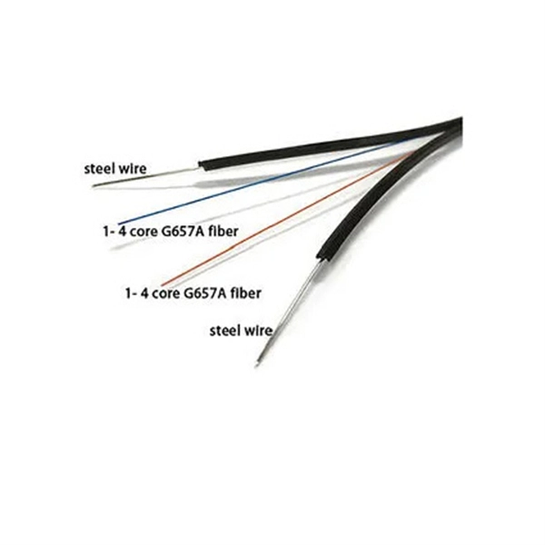
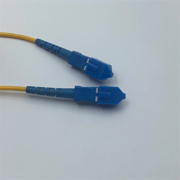
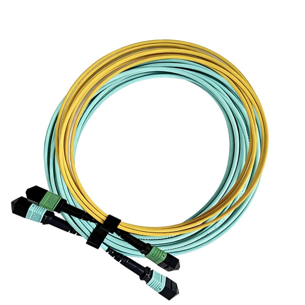
A fiber optic pigtail is a short length of optical fiber cable with a factory-terminated connector on one end and a bare, exposed fiber on the other. Executive Summary: A fiber optic pigtail is one of the most commonly specified yet least understood components in structured cabling. Get the wrong connector type, the wrong polish, or skip proper fusion splicing technique—and you're looking at elevated signal loss, increased back reflection, and a. According to Cambridge Dictionary, to splice means to “join the ends of something so that they become one piece. ” So in essence, fiber optic splicing is a process used to join two separate fiber optic cables together. There are numerous use cases for fiber optic splicing. Through splicing, fiber. Fiber optic joints or terminations are made two ways: 1) splices which create a permanent joint between the two fibers or 2) connectors that mate two fibers to create a temporary joint and/or connect the fiber to a piece of network gear. Either joining method must have three primary characteristics. Splicing allows you to restore or expand fiber networks while maintaining signal integrity. When done right, splicing ensures minimal loss and long-lasting performance. These terminations must be of the right style, installed in a.
[PDF]

IEC 61439 is a standard developed by the International Electrotechnical Commission (IEC) that covers design verification for low-voltage electrical products and assemblies. Busbar design within Medium Voltage (MV) switchgear is a critical aspect, fundamentally ensuring the safe, reliable, and efficient operation of power systems. The IEC 61439. Annex D was introduced in the april 2020 version of UL 508A. It clarifies what was previously common but not formally correct practice. A manufacturer of electrical automation panels is not required to use a certified busbar system or to subject it to short-circuit tests, provided that it complies. A recent study found that there are roughly 30,000 arc flash incidents in the United States each year, many of which are powerful enough to cause significant injury to workers and costly damage to equipment2. The adoption of busbar power distribution systems on a global scale has accelerated in the. Double spacer for easy leveling and connecting on both sides (snubber. ). From time to time we are asked what bus spacings are required by ANSI standards for switchgear. Those who ask are frequently surprised by the answer: None. ANSI switchgear standards are generally performance standards. Dielectric tests, power frequency withstand for all voltages and impulse.
[PDF]
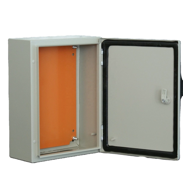
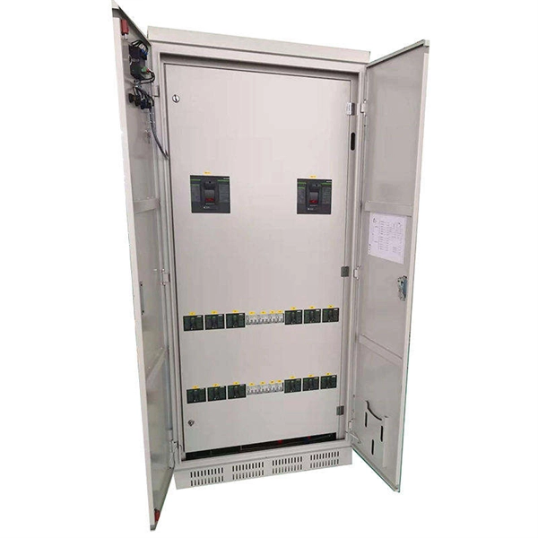
Design requirements for low voltage distribution boxes cover NEC, IEC, and safety standards to ensure reliable, compliant electrical installations. You must make safety your top priority when working with low voltage distribution boxes. Among the most widely recognized frameworks governing electrical panel design are the IEC (International Electrotechnical Commission) standards, particularly the IEC 61439 series, which defines the requirements for low-voltage switchgear and controlgear assemblies. In this blog, we explore the. Standards are for reference only. All new extension or modifications require an approved design and a preconstruction meeting with EWEB prior to installation. Need more information on how to get a design? Contact us at distributionengineering@eweb. NEC Article 408 covers switchboards, switchgear, and Panelboards installation and applications. Redesigned to improve safety, product longevity and appearance over time. Note: Eaton recommends mounting redesigned enclosures with at least six inches of clearance between adjacent structures to provide adequate access to side bolts. a Applicable for type LWPQ only. A distribution box is the heart of any electrical system. It takes the incoming power and safely distributes it to different circuits throughout your building. Whether in a home or an industrial facility, this box keeps.
[PDF]

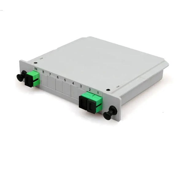
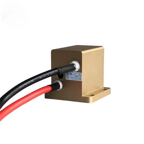
To meet the needs of multi-way power distribution applied to high-power solid-state sources, a multi-way power distribution device based on coaxial waveguide is designed and studied. In this work, two dynamically tunable power dividers using waveguide ENZ media are proposed by precisely modulating the internal magnetic field and the widths of the output waveguides. The first approach features a mechanically reconfigurable ring-shaped ENZ waveguide. By analyzing the transmission characteristics of coaxial waveguides and by applying the theory of impedance. In this paper, an E -plane stepped-impedance transformer and Y-junction bifurcation are used to form a waveguide power divider with ceramic substrate loaded with thin film resistors. This structure is realized high isolation in V-band by inserting a ceramic substrate at the H -plane center of the. A numerical model of an equal power divider based on the 4-branch single-mode waveguide is proposed. This proposed design does not require extra fabrication process and supplementary structure modification compared to other typical multibranch waveguides. The condition of uniform output power.
[PDF]
There are temporary splices that use a sleeve and index matching jell but they are expensive and if you don't prepare the fibre ends properly they won't work anyway. The correct fix will probably be a Field Tech with a fusion splicer and cleaver which is thousands of dollars worth. The most detailed cold splicing prodcedures for broken fiber optic cable. You can source the fiber optic cables or other cabling products from the manufacturer supplier at factory prices on site: https://www. more The most detailed cold splicing prodcedures for broken. Fiber optic joints or terminations are made two ways: 1) splices which create a permanent joint between the two fibers or 2) connectors that mate two fibers to create a temporary joint and/or connect the fiber to a piece of network gear. Either joining method must have three primary characteristics. Before splicing or connecting, clean the stripped and cleaved fiber ends using alcohol and lint-free wipes to remove dust, oil, or other contaminants. Clean fiber ends ensure low-loss, reliable connections. For network managers and technicians, a poor splice can lead to significant signal degradation, network downtime, and costly troubleshooting. At Turn-Key. Whether you are building a new backbone, restoring service after damage, or upgrading an existing route, disciplined fiber optic splicing techniques determine signal integrity, longevity, and operational uptime. These terminations must be of the right style, installed in a.
[PDF]
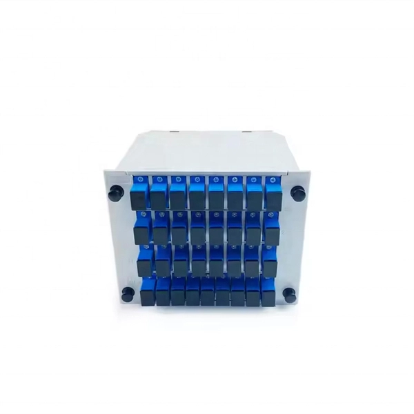
Fiber optic splicing metal box for 8 adaptors SC simplex, LC duplex or E2000. Wall mounting enabled. All products' documentation is published in PDF (Portable Document Format), which requires Adobe Reader (ver. 5 and newer) software for viewing. Though we pay utmost attention, we cannot guarantee. Every payment you make on Alibaba. com is secured with strict SSL encryption and PCI DSS data protection protocols Claim a refund if your order doesn't ship, is missing, or arrives with product issues. The HAILE 8 Optical Fiber Termination Box P1-8-FC is an essential fiber optic distribution frame designed to manage and protect fiber optic cables in various networking environments. This termination box is equipped with 8 ports that support FC connectors, making it ideal for high-performance. Fiberlink provides fiber optic splice box products for FTTH solution, including fiber terminal box, fiber splice enclosure, optical distribution box. FBR-11607 Fiber-Optic Distribution Box, 8-Core is a high quality product by Bud Industries used for electronic enclosure applications.
[PDF]
On average, a single fusion splice can take anywhere from 10 to 30 minutes, including preparation and testing. The answer isn't always straightforward, as it depends on various factors, including the type of fiber, the splicing method, and the level of expertise of the technician. Before we dive into the timeline, it's essential to understand the splicing process itself. Fiber splicing involves several. Fusion splicing refers to a method of joining two optic fibers together by means of heat, often an electric arc, which fuses the glass ends. It is the technique that has the least insertion loss and almost no back reflection, hence ensuring strong connections over a long period. A welding machine. This is typically done when the cable length is insufficient or when the fiber network is damaged and needs restoration. Unlike connectors, which are used for temporary joints, splicing creates a permanent, low-loss connection. This process is essential in telecommunications for extending network reach or repairing damaged sections without replacing entire cables. Splicing preserves the integrity and efficiency of the fiber optic network, offering a cost-effective solution for. A chart developed by Fiber Optic Association master instructor Joe Botha helps technicians calculate the amount of time it will take to conduct a fusion-splcing project. The FOA mentioned the chart in its November 2011 newsletter, stating, "We've been asked many times, 'How long does it take to.
[PDF]
The medium sized closure shall accommodate up to 288 single fiber splices or 432 ribbon fiber splices. Buffer tubes shall not be subjected to a bend radius smaller. For protection against the outside plant environment and damage, splices require placement in a protective enclosure, usually called a splice closure. Splices are generally placed in a splice tray which is then placed inside a splice closure or integrated into a fiber pedestal for OSP. 2. Although a compact size, there is ample room to express 144 fiber cable. The FSDC series closures are fully sealed units which can be mounted on a. Fiber Splice Tray in Fiber Optic Splice Closure The fiber optic splice closure is component which is widely used in today's fiber optic network for outdoor applications and harsh environment. Fiber splice closures are not used occasionally — they are deployed extensively across every fiber network. The exact quantity depends on population density, network topology, and regional infrastructure planning. Below is a simplified example based on a 10 km coverage area serving approximately. Amphenol fiber optic sealed drop closures provide a versatile and functional cost-effective solution for FTTH network connections to the subscriber.
[PDF]
A splice box (also known as splice distributor) is a housing in which fiber optic cables begin or end. Fiber optics are fanned out in splice boxes that are situated at the end of fiber optic transmission paths. It typically consists of two parts: an outer housing and an internal structure. The main components of a splice box are the splice cassette that picks up the fibers and. The fiber optic dome splice closure is well-suited for splicing, distributing variable optical cables, and splitting. The solid box shell and the main structure are built to withstand harsh environments. The dome closure also protects fiber optic cables from vibration, impact, stretching, twisting. Home » Professional Insights » Fiber Optic Splice Closure: A Complete Guide to Types, Structure, Applications, and Selection In real fiber optic networks, cables are rarely installed as one continuous, uninterrupted length. Along transmission routes—whether in access networks, metro networks, or. Big space for managing pigtails or splitters. The 12 Port Fiber Distribution Box can connect up to 2 optical cables, providing space for distributors and 12 fuses. It is equipped with 12 SC adapters and can work in outdoor environments. Data communication networks. Horizontal fiber optic splice closures, also known as optical cable splice boxes, play an important role in the communications industry. It is a must-have device in the construction of optical cable line projects.
[PDF]
The core principle of fiber optic splicing is to achieve low-loss, high-strength junctions between fiber ends. This involves three key steps: preparation, alignment, and bonding. Let's break it down technically:. At the core of this system's precision and reliability are Fiber Optic Splice Boxes—the unsung heroes that house and protect the delicate junctions where fiber cables are joined. The integrity of these enclosures is paramount to network performance. This guide optimizes the original text by delving. A splice box (also known as splice distributor) is a housing in which fiber optic cables begin or end. Key Functions Typical Applications ZION FTB Highlights In essence: The Fiber Terminal Box is an end-user termination device for small-scale distribution. ■ What Is a Fiber. Fiber optic cables are the lifeline of modern telecommunications, delivering high-speed data with minimal loss. However, installing and maintaining these networks requires seamless connections between fiber segments—a process known as fiber optic splicing. Understanding how it works is essential for anyone interested in telecommunications or network infrastructure. Essential for mending faults or scaling networks, splicing underpins the backbone of contemporary communications. In this comprehensive guide.
[PDF]
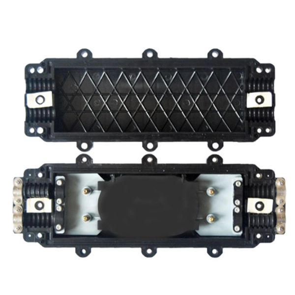
OPGW cable joint box installation involves several key stages: selecting the appropriate location, preparing both the cable and the joint box, splicing fibers, and sealing the joint box properly. Adhering to these steps ensures optimal performance and longevity of the telecommunications system. Optical fiber junction boxes are essential components in outdoor optical fiber cable installations. In this article, we will discuss the necessary steps and best practices. The Indoor/Outdoor Splice Box is a wall-mounted, indoor/outdoor fiber splice enclosure for centralized splice-only applications. These boxes are well suited as optical cable splice collection points for MDU (Multi-Dwelling Unit) residential fiber network applications, MTU (Multi-Tenant Unit). The installation of an optical cable junction box is crucial in ensuring the integrity and performance of optical networks. As we enter 2024, adhering to best practices not only enhances system reliability but also mitigates potential issues that can affect customer experiences. Installing a fiber optic splice closure efficiently and effectively requires attention to detail and. AFL's SB01 splice enclosure provides protection from all types of elements. From weather to bullets, the iron and steel construction requires no additional protective covering. Furnished with four plugged cable ports (2 aluminum and 2 plastic) for either All-Dielectric Self-Supporting (ADSS) or.
[PDF]