A relay protection tester is a core device used to verify the performance of relay protection devices. Its working principle can be summarized as “signal excitation – behavior detection. ”. Circuit principle of relay protection tester 1, input AC220V power output control relay K1 is approved by the insurance into the dual voltage regulator for T1 input carbon brush, through large knob to adjust the power into the isolation transformer T1 T2 (part-time riser), heat flow device points. When the transformer wiring type is Y/Y (Y0), the test wiring is very simple: when testing phase A, the tester IA is connected to the phase A of the high voltage side, and the tester IB is connected to the phase a of the low voltage side. ” The tester has a built-in high-precision programmable power supply, capable of simulating various operating. This handbook covers the code of practice in protection circuitry including standard lead and device numbers, mode of connections at terminal strips, colour codes in multicore cables, dos and donts in execution. The following is a detailed summary. This Playlist is assigned to sessions of protection Relays Principles. First, a description of Simple Functions.
[PDF]

The total interruption time for a modern high-voltage SF6 circuit breaker is typically between 40 to 60 milliseconds on a 50Hz grid, or 2 to 3 cycles. This is the total time from the trip signal to the final arc extinction, a critical parameter for grid safety. While knowing the total time is a. When a SF6 circuit breaker (CB) hits its critical low pressure, its fault interrupting capability can be compromised. Most TOs protect against this by either auto-opening the CB prior to reaching the critical low-pressure level or by blocking the CB from tripping (when it reaches the critical. The protected zone is defined and limited by different things depending on the protection function. Definite time delay means that the protection operate time dose not change or depend on the fault type or the fault current magnitude. Instead of oil, air, or a vacuum, a sulfur hexafluoride circuit breaker uses sulfur hexafluoride (SF 6) gas to cool and quench the. Page 1 Content Instruction Manual circuit- breaker GL317 With spring operating mechanisms FK3- 4 Administrator First issue Compiled by Approved by 19- 11- 2012 J. Texier Imagination at work Grid Solutions 04- 2017 D1736EN/03 GE Information 1/10. Page 2 Content Instruction Manual This. A comparison of the time it takes protective devices to operate when certain levels of normal or abnormal current pass through them. LV circuit breaker ratings.
[PDF]

The standard industry practice is to set overload relays at 125% of the motor's nameplate Full Load Ampere (FLA) rating. Plug Setting Multiplier (PSM) indicates how many times the determined relay secondary current (typically the CT secondary) exceeds the relay pickup (plug) current. It is the key quantity utilized in IDMT (inverse definite minimum time) curves to calculate the basic operating time. PSM (Plug Setting. An overload relay is a crucial device for motor control, designed to prevent motors from overheating or suffering winding damage due to excessive current. Motor overload relays protect against sustained overcurrent conditions that cause dangerous overheating, insulation breakdown, and premature. Overload relays protect motors and equipment from thermal damage caused by prolonged overcurrent conditions. IEC 60255 defines standards, formulas, and performance requirements, enabling accurate calculations and real-world applications. How is the overload relay current calculated? Why include. Setting motor overload relays correctly is critical for protecting AC induction motors from sustained overcurrent conditions while avoiding nuisance trips during normal starting transients. This occurred when the relay F was set at 1. The complaint was that the relay tripped instantly on overload when the thermal damage curve show plotted for a specific current that was less t an.
[PDF]
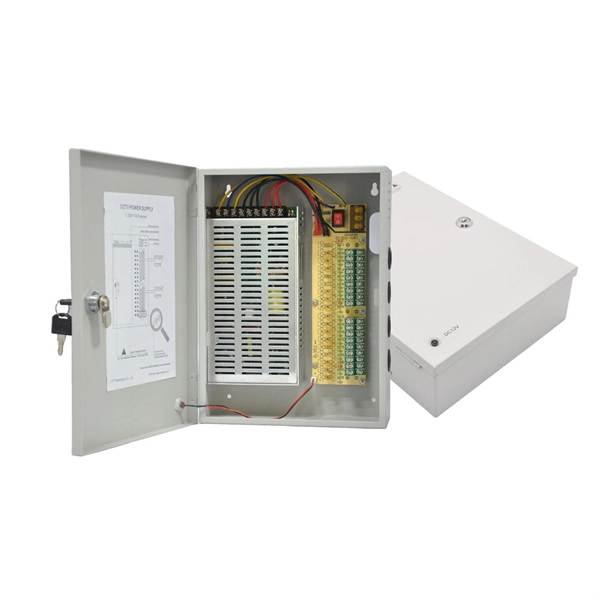
Browse enclosures designed for easy installation and cooling of enclosed equipment. Crafted from durable pre-galvanized steel, these boxes are designed to house wiring devices such as switches or outlets. With RACO's Switch Electrical Boxes, convenience is key. The device mounting holes are pre-tapped to. Power and Low Voltage Box For New Construction, Nail On. Low Voltage Side Provides Combination 1/2" and 3/4" Knockout. This intelligent fire emergency lighting system utilizes a centralized power controller distribution box, complying with the GB-17945-2010 standard, and provides over 90 minutes of emergency runtime. The system comprises an emergency lighting controller, a centralized power supply (EPS), and. Electrical Junction Box, Ventilated Design, Cable Grommets, Indoor/Outdoor Use with Mounting Panel & Hinged Cover. (Grey Cover, 13"x13"x5. 1") Need help? Streamline your home wiring and media setup with low voltage panel boxes. “Value After Rebate*” is the price or sale price minus the future rebate discounts. Valid on merchandise; excludes purchase of gift cards, rentals. For new construction and retrofit projects! Arlington's convenient combo box has power and low voltage openings in the same box, saving you time and money. LVD2, designed for new construction, comes with nails in place, ready for attachment to wood studs. Holes in the front flanges allow for screw.
[PDF]
If a fault is detected, the relay will send signals to adjacent relays and circuit breakers, allowing the closest breaker to trip first while other breakers delay their operation. This selective coordination helps isolate the faulted zone while maintaining the power supply to the. A protection relay is a crucial component of electrical systems that safeguard infrastructure, employees, and equipment from electric problems and malfunctions. It functions as a watchdog by constantly surveying multiple system components including voltage, current, frequency, and phase angle. It. A protective relay is the vigilant guardian of electrical networks, constantly monitoring and analyzing electrical parameters to detect abnormal events. Acting as the first line of defence, it swiftly detects faults, such as short circuits or overcurrents. It triggers protective actions to isolate. In electrical engineering, a protective relay is a relay device designed to trip a circuit breaker when a fault is detected. : 4 The first protective relays were electromagnetic devices, relying on coils operating on moving parts to provide detection of abnormal operating conditions such as. A protective relay is an intelligent device that senses abnormal electrical conditions, such as overcurrent, under-voltage, or frequency deviations. It initiates the operation of circuit breakers to isolate the affected section.
[PDF]
Protection is accomplished by application of a definite time overcurrent option. Current setting is greater than full load current but is lower than the motor starting current. Should a motor stall whilst running, or fail to start, due to excessive. When a motor starts, it can draw 6-8 times its full-load current for a brief period, creating significant challenges for circuit protection, voltage regulation, and system capacity planning. Understanding motor starting characteristics is essential for proper breaker sizing, motor protection relay. These time-overcurrent elements support the IEC and U. (IEEE) time-overcurrent characteristics. Electromechanical disc reset capabilities are provided for all time-overcurrent elements. protection and fault clearance in abnormal situations. The main features of the motor relay include thermal overload protection, motor start-up time supervision, locked rotor protec ion, and protection against too frequent motor starts. Addi ionally, differential protection can also be included. In order to prevent damage to the contactor, the maximum peak let-through current (Ip ) and maximum clearing energy (I2t) (amps2 seconds) of the fuse must be less than the equivalent ratings for the contactor. The clearing time and let-through characteristics of the fuse must be considered when.
[PDF]
The article provides an overview of protective relaying principles and their applications for high-voltage power system components. It covers the protection methods for generators, transformers, buses, and transmission lines using various relay types to detect and. Protective relaying is the backbone of fault detection and system isolation in As transmission systems grow increasingly complex with integration of renewables and smart technologies, the design, configuration, and application of protective relays have become more critical than ever. This article. tensify their search for reductions in capital investment and operating expenses. Faced with the continuing demand for more and more power in an environmentalist era, many operating companies are seeking, among other things, a means for supplying eliable power with fewer transmission lines and. SIPROTEC 7SD82 provides compact, cost-optimized line differential protection for medium- and high-voltage systems. It ensures safety with 3-pole tripping in 19 ms and high availability via conformal coating. The modular SIPROTEC 7SD86 is specifically designed for line differential protection of. Still deciding? Get samples first! Order sample Still deciding? Get samples first! Order sample. In HV (High Voltage) and MV (Medium Voltage) substations, relay protection safeguards critical assets such as transformers, circuit breakers, and lines. Effective relay protection depends on.
[PDF]
Electromechanical protective relays at a hydroelectric generating plant. The relays are in round glass cases. The rectangular devices are test connection blocks, used for testing and isolation of instrument transformer circuits.OverviewIn, a protective relay is a device designed to trip a when a is detected. The first protective relays were electromagnetic devices, relying on coils operating on moving par. Electromechanical protective relays operate by either, or. Unlike switching type electromechanical with fixed and usually ill-defined operating voltage thresholds. Electromechanical relays can be classified into several different types as follows: "Armature"-type relays have a pivoted lever supported on a hinge or knife-edge pivot, which carries a moving contact. These relays may.
[PDF]
Below is a list of best universities in the United States ranked based on their research performance in Firefighting and Fire Science. Explore the best colleges with fire protection and prevention degrees. Read more on how this ranking was calculated. A graph of 221K citations received by 5. 06K academic papers made by 48 universities in the United States was used to calculate publications' ratings, which then. Looking for colleges with a Fire Protection Major? See a list of colleges with Fire Protection here to evaluate admissions data, tuition, rankings and more. Access exclusive rankings for colleges and universities around the country. Our AI model can make mistakes. Double check important details. What's on this page: * Degree-Level Rankings Your choice of fire. The educational requirements for a protective relay technician are a combination of high school diploma, certificate, and associate degree. According to the data, a certificate in a relevant field is held by 50. 33% of protective relay technicians, while 39. 1% have an associate degree. Fire protection and safety technology majors are the most popular in California (60 schools), North Carolina (23 schools), Florida (19 schools), and Texas (13 schools). The best protection.
[PDF]
Earth fault protection based on measured or calculated residual current values: If a breaker fails to be triggered by a tripping order, as detected by the non-extinction of the fault current, this backup protection sends a tripping order to the upstream or adjacent breakers. In electric power systems and industrial automation, ANSI Device Numbers can be used to identify equipment and devices in a system such as relays, circuit breakers, or instruments. The device numbers are enumerated in ANSI / IEEE Standard C37. 2 Standard for Electrical Power System Device Function. In North America protective relays are generally referred to by standard device numbers. ANSI IEEE Standard Device Numbers are below: (the more commonly used ones are in bold) 86T is a Lockout Relay for a. The ANSI standard device numbers ( As per ANSI/IEEE standard C37. 2) are used in the design of an electrical power system. The list of ANSI device numbers with their acronyms is as given below. Save my name, email. The protection and control devices in electrical equipment can be referred to by numbers, with appropriate suffix letters when necessary, according to the functions they perform. Even in those parts of the world where IEC standards are predominate, the use of ANSI numbering. There are two methods for indicating protection relay functions in common use. The functions are supplemented by letters where amplification of the function is required. The other is given in IEC 60617 and uses.
[PDF]

An analog accessory for use in a system for testing protection relays is provided, comprising inputs connectable to the current outputs of a test-set for protection relays and voltage outputs connectable to a protection relay to be tested. The register contains national patents and information related to European Patents validated in Malta. It currently provides European patent numbers, filing dates, titles, abstracts, classifications, applicants, bibliographic data, status, priorities, expirations, annuity/renewal fees. The utility model discloses a power plant relay protection tester, belonging to the technical field of relay protection testers, which comprises a relay protection tester body and a shell for placing the relay protection tester body, wherein a partition plate is arranged in the shell, a driving. Application to amend a patent application or registration. Convert a European patent application to a National patent. Request an extension of a time limit for the submission of patent documents. By providing an electric circuit adapted to convert current. Background Relays and metering are an important part of power generation, power transmission, and power con- sumption in electric power systems and the power grid. Relays provide monitoring and protection of equipment and personnel.
[PDF]

In this guide, we'll explore what protection relays are, how they're classified, the types available, and how they work with instrument transformers to create secure zones of protection. What Is a Protection Relay?. Protective Relay Definition: A protective relay is an automatic device that senses abnormal conditions in electrical circuits and triggers actions to isolate faults. Types of Protective Relays: Protective relays are categorized by their mechanism (electromagnetic, static, mechanical) and function. This article covers various types of protective relays, such as overcurrent, directional, and differential relays, highlighting their operating characteristics and applications in electrical systems. They don't just protect equipment; they ensure safety, prevent downtime, and save lives. A protective relay is a device that detects the fault and initiates the operation of the circuit breaker to isolate the defective element from the rest of the. The rectangular devices are test connection blocks, used for testing and isolation of instrument transformer circuits.
[PDF]
With its novel and future-oriented approach our software solution for system-based protection testing, performs tests independent of relay type, relay manufacturer, and offers extensive parameter settings. It focuses on. With its novel and future-oriented approach our software solution for system-based protection testing, performs tests independent of relay type, relay manufacturer, and offers extensive parameter settings. It focuses on the correct behavior of the protection system by simulating realistic events in the power system. RelaySimTest. Specifically designed for settings-based protection testing with a high degree of automation, our modular software Test Universe offers numerous functions and application-optimized test modules that save you valuable time. Test Universe. Use CMControl P for quick and easy manual testing. CMControl P is available as an App for Android tablets and Windows PC, or as a dedicated front-end device. CMControl P. With this software the CMC test set becomes a multifunctional measurement and recording unit. You can use EnerLyzer in parallel with the software used for operating your CMC. Enerlyzer. The open programming interface CMEngine enables you to integrate the CMC test sets into your own testing environment and control them within any type of application. CMEngine.
[PDF]
Every protection system which isolates a faulty element is required to satisfy four basic requirements: (i) reliability; (ii) selectively; (iii) sensitivity; and (iv) speed of operation. Protection system is an extremely important part of the power system as it is provided to operate under abnormal conditions to prevent failure or isolate trouble and limit its effect. It is designed to detect and isolate faults or abnormal conditions within the system to prevent damage, minimize downtime, and maintain power quality. This. Relay protection primarily operates on the principle of utilizing the variations in electrical quantities (such as current, voltage, power, frequency, etc. It emphasizes selectivity, coordination, fault response, and system behavior rather than individual relay devices. Relay protection is often misunderstood as a. Protective relays and devices have been developed over 100 years ago to provide “lastline”of defense for the electrical systems. They are intended to quickly identify a fault and isolate it so the balance of the system continue to run under normal conditions. The selection and applications of. Abstract: Information on the concepts of protection of ac transmission lines is presented in this guide. Many important issues, such as coordination of settings, operating times, characteristics of.
[PDF]
Thermal overload relays are widely used to protect motors. These devices work on the thermal effect principle. A thermal relay is an electromechanical device that detects temperature changes in electrical circuits, protecting equipment from overload and overheating. Thermal relays are critical components in electrical systems, designed to protect motors and other electrical equipment from damage caused by. Thermal Relay Definition: A thermal relay is defined as a device that uses the unequal expansion rates of metals in a bimetallic strip to detect overcurrent conditions. Working Principle: The thermal relay operates by heating a bimetallic strip, causing it to bend and close normally open contacts. So, the thermal relay is one of the types of the relay, used to provide complete safety against single phasing, unbalanced voltages & overloads. Thermal relays are the perfect solution for providing protection to motors which provides the most precise tripping for the electric motor during single. Introduction — The Core Device Protecting Industrial Motors Thermal overload relays are one of the most essential protection components in industrial motor circuits. Correct understanding and configuration ensure equipment safety and longevity. Its performance matches the actual heating characteristics of.
[PDF]