A relay protection tester is a core device used to verify the performance of relay protection devices. Its working principle can be summarized as “signal excitation – behavior detection. ”. Circuit principle of relay protection tester 1, input AC220V power output control relay K1 is approved by the insurance into the dual voltage regulator for T1 input carbon brush, through large knob to adjust the power into the isolation transformer T1 T2 (part-time riser), heat flow device points. When the transformer wiring type is Y/Y (Y0), the test wiring is very simple: when testing phase A, the tester IA is connected to the phase A of the high voltage side, and the tester IB is connected to the phase a of the low voltage side. ” The tester has a built-in high-precision programmable power supply, capable of simulating various operating. This handbook covers the code of practice in protection circuitry including standard lead and device numbers, mode of connections at terminal strips, colour codes in multicore cables, dos and donts in execution. The following is a detailed summary. This Playlist is assigned to sessions of protection Relays Principles. First, a description of Simple Functions.
[PDF]

The total interruption time for a modern high-voltage SF6 circuit breaker is typically between 40 to 60 milliseconds on a 50Hz grid, or 2 to 3 cycles. This is the total time from the trip signal to the final arc extinction, a critical parameter for grid safety. While knowing the total time is a. When a SF6 circuit breaker (CB) hits its critical low pressure, its fault interrupting capability can be compromised. Most TOs protect against this by either auto-opening the CB prior to reaching the critical low-pressure level or by blocking the CB from tripping (when it reaches the critical. The protected zone is defined and limited by different things depending on the protection function. Definite time delay means that the protection operate time dose not change or depend on the fault type or the fault current magnitude. Instead of oil, air, or a vacuum, a sulfur hexafluoride circuit breaker uses sulfur hexafluoride (SF 6) gas to cool and quench the. Page 1 Content Instruction Manual circuit- breaker GL317 With spring operating mechanisms FK3- 4 Administrator First issue Compiled by Approved by 19- 11- 2012 J. Texier Imagination at work Grid Solutions 04- 2017 D1736EN/03 GE Information 1/10. Page 2 Content Instruction Manual This. A comparison of the time it takes protective devices to operate when certain levels of normal or abnormal current pass through them. LV circuit breaker ratings.
[PDF]

An analog accessory for use in a system for testing protection relays is provided, comprising inputs connectable to the current outputs of a test-set for protection relays and voltage outputs connectable to a protection relay to be tested. The register contains national patents and information related to European Patents validated in Malta. It currently provides European patent numbers, filing dates, titles, abstracts, classifications, applicants, bibliographic data, status, priorities, expirations, annuity/renewal fees. The utility model discloses a power plant relay protection tester, belonging to the technical field of relay protection testers, which comprises a relay protection tester body and a shell for placing the relay protection tester body, wherein a partition plate is arranged in the shell, a driving. Application to amend a patent application or registration. Convert a European patent application to a National patent. Request an extension of a time limit for the submission of patent documents. By providing an electric circuit adapted to convert current. Background Relays and metering are an important part of power generation, power transmission, and power con- sumption in electric power systems and the power grid. Relays provide monitoring and protection of equipment and personnel.
[PDF]
If a fault is detected, the relay will send signals to adjacent relays and circuit breakers, allowing the closest breaker to trip first while other breakers delay their operation. This selective coordination helps isolate the faulted zone while maintaining the power supply to the. A protection relay is a crucial component of electrical systems that safeguard infrastructure, employees, and equipment from electric problems and malfunctions. It functions as a watchdog by constantly surveying multiple system components including voltage, current, frequency, and phase angle. It. A protective relay is the vigilant guardian of electrical networks, constantly monitoring and analyzing electrical parameters to detect abnormal events. Acting as the first line of defence, it swiftly detects faults, such as short circuits or overcurrents. It triggers protective actions to isolate. In electrical engineering, a protective relay is a relay device designed to trip a circuit breaker when a fault is detected. : 4 The first protective relays were electromagnetic devices, relying on coils operating on moving parts to provide detection of abnormal operating conditions such as. A protective relay is an intelligent device that senses abnormal electrical conditions, such as overcurrent, under-voltage, or frequency deviations. It initiates the operation of circuit breakers to isolate the affected section.
[PDF]
of relay protection coordination for a PV power plant connected to the distribution network is presented. In recent years, installation of PV power plants in the distribution network has increased significantly. I.
[PDF]
Specifically designed for settings-based protection testing with a high degree of automation, our modular software Test Universe offers numerous functions and application-optimized test modules that save yo.
[PDF]
The relay block comprises the two protection units, phase protection unit and earth protection unit. When the value of the current in any of the phases is greater than the pick up value, the phase protecti.
[PDF]
Thermal overload relays are widely used to protect motors. These devices work on the thermal effect principle. A thermal relay is an electromechanical device that detects temperature changes in electrical circuits, protecting equipment from overload and overheating. Thermal relays are critical components in electrical systems, designed to protect motors and other electrical equipment from damage caused by. Thermal Relay Definition: A thermal relay is defined as a device that uses the unequal expansion rates of metals in a bimetallic strip to detect overcurrent conditions. Working Principle: The thermal relay operates by heating a bimetallic strip, causing it to bend and close normally open contacts. So, the thermal relay is one of the types of the relay, used to provide complete safety against single phasing, unbalanced voltages & overloads. Thermal relays are the perfect solution for providing protection to motors which provides the most precise tripping for the electric motor during single. Introduction — The Core Device Protecting Industrial Motors Thermal overload relays are one of the most essential protection components in industrial motor circuits. Correct understanding and configuration ensure equipment safety and longevity. Its performance matches the actual heating characteristics of.
[PDF]

A protection relay tripping circuit connects relays to breakers for fast fault isolation. Key components include trip/close coils and anti-pumping relays. Proper design, testing, and maintenance ensure reliable overcurrent, differential, and auto-reclosing protection in power. The protection relay tripping circuit refers to the critical electrical control loop that executes trip/close commands from protective relays to circuit breakers, ensuring rapid fault isolation in power systems. Essential. Electromechanical protective relays at a hydroelectric generating plant. The relays are in round glass cases. In electrical engineering, a protective relay is a relay device. A protective relay is an intelligent electrical device designed to detect faults in power systems and initiate corrective actions such as tripping a circuit breaker. Its main purpose is to safeguard electrical equipment like transformers, generators, and transmission lines from damage due to. By definition, a protective relay is a switchgear device that detects faults and initiates the circuit breaker operation to isolate the problematic component of the system. Electrical values are measured by these relays to determine abnormal circumferences of a circuit. It functions as a watchdog by constantly surveying multiple system components including voltage, current, frequency, and phase angle.
[PDF]
Relays may be fitted with a "target" or "flag" unit, which is released when the relay operates, to display a distinctive colored signal when the relay has tripped.OverviewIn, a protective relay is a device designed to trip a when a is detected. The first protective relays were electromagnetic devices, relying on coils operating on moving par. Electromechanical protective relays operate by either, or. Unlike switching type electromechanical with fixed and usually ill-defined operating voltage thresholds. Electromechanical relays can be classified into several different types as follows: "Armature"-type relays have a pivoted lever supported on a hinge or knife-edge pivot, which carries a moving contact. These relays may.
[PDF]
Earth fault protection based on measured or calculated residual current values: If a breaker fails to be triggered by a tripping order, as detected by the non-extinction of the fault current, this backup protection sends a tripping order to the upstream or adjacent breakers. In electric power systems and industrial automation, ANSI Device Numbers can be used to identify equipment and devices in a system such as relays, circuit breakers, or instruments. The device numbers are enumerated in ANSI / IEEE Standard C37. 2 Standard for Electrical Power System Device Function. In North America protective relays are generally referred to by standard device numbers. ANSI IEEE Standard Device Numbers are below: (the more commonly used ones are in bold) 86T is a Lockout Relay for a. The ANSI standard device numbers ( As per ANSI/IEEE standard C37. 2) are used in the design of an electrical power system. The list of ANSI device numbers with their acronyms is as given below. Save my name, email. The protection and control devices in electrical equipment can be referred to by numbers, with appropriate suffix letters when necessary, according to the functions they perform. Even in those parts of the world where IEC standards are predominate, the use of ANSI numbering. There are two methods for indicating protection relay functions in common use. The functions are supplemented by letters where amplification of the function is required. The other is given in IEC 60617 and uses.
[PDF]
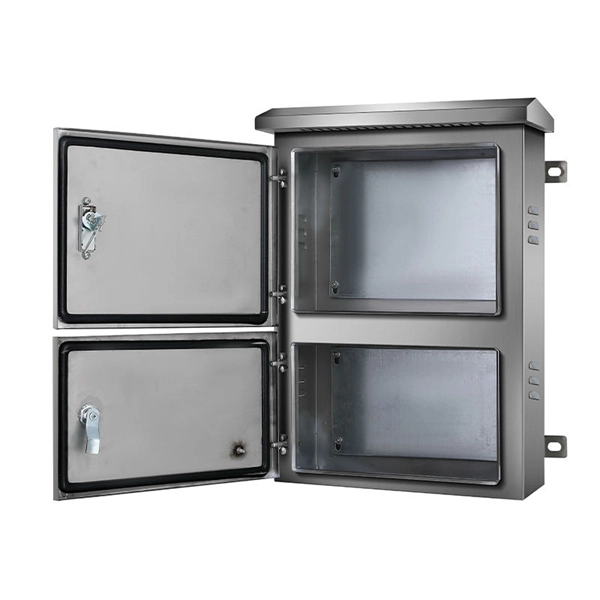
Single Line Drawing of the LV Distribution Network with feeder pillars and distribution boxes, showing cable length, size, voltage drop, and percentage voltage drop. All orders over MVR 300 qualify for free delivery, while orders under MVR 300 are subject to a MVR 50 delivery fee. In addition, we do delivery of goods up to Jetty/boat. In cases where the goods are requested to be delivered to a vessel, details. Let us help you with your questions and queries. Send a message to Viber: 7317894 Promotions, new products and sales. Directly to your inbox. If Datasheet includes multiple models, the model number should be highlighted Datasheet of Transmission equipment. Busbar configuration, dimensions, materials and rating. Single Line. © 2024 E-Talk Maldives. Nuomak is proud to announce a new cooperation with a client in the Maldives, for whom we have manufactured PS cabinets, MCCBs, and transparent waterproof electrical distribution boxes. These products are specially designed to meet the challenges of high humidity, salt spray, and harsh coastal. Can't find the product you need? Please give us feedback Dongfeng-covering various types of distribution boxes_rich and diverse product system, covering various types of distribution boxes and cabinet products.
[PDF]
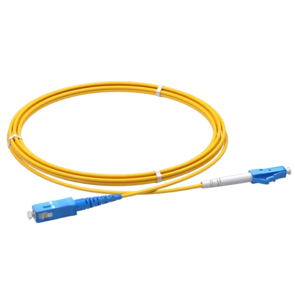
Temukan daftar Supplier, Pabrik, Importir, Distributor dan Toko Kabel Patch Cord untuk wilayah Indonesia . Update setiap hari, harga kompetitif dan layanan terpercaya. High performance and high quality connectors cable assembly are required for next generation optical networks to assure long term reliability for demanding applications such as FTTx, DWDM, 100G, CATV and etc. The connector assemblies are IEC, Telcordia and RoHS compliant. The termination passed. Prima Akses Digital Indonesia, is a Indonesian local company specialized in fiber optic product development and solution service for network infrastructure. Prima Akses Digital Indonesia, established in 2020, is supported by several partner companies and management which have been experienced in.
[PDF]
Browse enclosures designed for easy installation and cooling of enclosed equipment. Crafted from durable pre-galvanized steel, these boxes are designed to house wiring devices such as switches or outlets. With RACO's Switch Electrical Boxes, convenience is key. The device mounting holes are pre-tapped to. Power and Low Voltage Box For New Construction, Nail On. Low Voltage Side Provides Combination 1/2" and 3/4" Knockout. This intelligent fire emergency lighting system utilizes a centralized power controller distribution box, complying with the GB-17945-2010 standard, and provides over 90 minutes of emergency runtime. The system comprises an emergency lighting controller, a centralized power supply (EPS), and. Electrical Junction Box, Ventilated Design, Cable Grommets, Indoor/Outdoor Use with Mounting Panel & Hinged Cover. (Grey Cover, 13"x13"x5. 1") Need help? Streamline your home wiring and media setup with low voltage panel boxes. “Value After Rebate*” is the price or sale price minus the future rebate discounts. Valid on merchandise; excludes purchase of gift cards, rentals. For new construction and retrofit projects! Arlington's convenient combo box has power and low voltage openings in the same box, saving you time and money. LVD2, designed for new construction, comes with nails in place, ready for attachment to wood studs. Holes in the front flanges allow for screw.
[PDF]
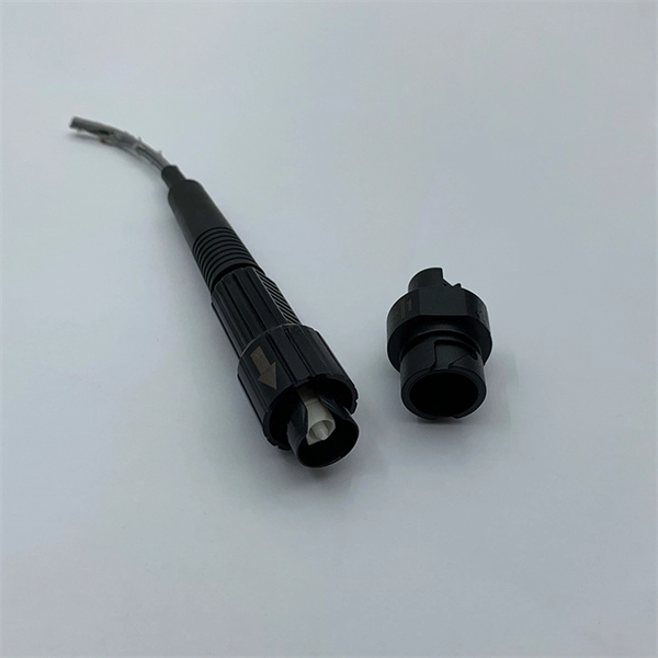
A practical, engineering-focused guide to planning and installing underground fiber optic cables with the right cable structure, trench design and protection level for long-life, low-risk networks. Match trench method with the correct underground fiber structure (GYTS . Installing fiber underground is one of the most durable ways to protect a network's backbone — when it's done right. Direct-burial fiber cable eliminates the need for continuous conduit runs and can be faster and more cost-effective on long, open runs. But because the cable sits in soil exposed to. 1. 01 This procedure provides general information for the installation of Prysmian fiber optic cables in direct buried applications. The methods described are intended for guideline use only, as it is impossible to cover all the various conditions that may arise during an installation. Individual. ion) and “ Installed” (after installation). The following formulas may be used to determine general guidelines for installing Corning Optical Communications fiber optic cable; however, refer to the cable specifi simply double the minimum working bend radius. Split cable guides and split 40-in. Fiber optic cable transmits data as pulses of light through thin strands of glass, offering superior bandwidth and distance capabilities compared to traditional copper wiring.
[PDF]