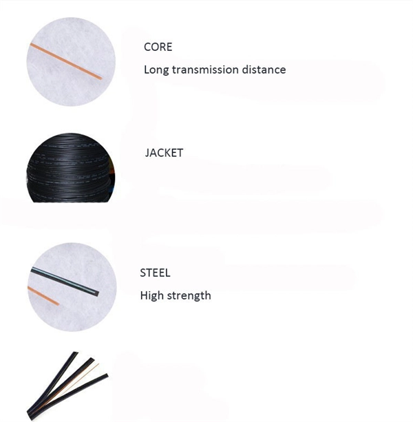
Patch cords, also known as jumper cables or fiber optic jumpers, are short lengths of fiber optic cable used to connect devices within a fiber optic network. They play a crucial role in establishing reliable and high-speed data transmission between equipment such as switches . The fiber optic patch cable must, therefore, be carefully considered. Behind its slender appearance lies the fusion of core types, connector types, and polish levels, each chosen for a specific application. Choosing the right cable thus boils down to educating oneself about fiber optic patch cable. As networks move to higher speeds and higher density, choosing the right fiber optic patch cords becomes critical to the reliability of your system. At ZION Communication, we design and manufacture a full range of fiber patch cords for: This guide will help you quickly understand the main types of. These short fiber optic cords connect transceivers, switches, patch panels, and servers. Without them, even the best optical modules and switches cannot deliver performance. In today's high-speed data transmission era, fiber optic patch cords have become essential components in telecommunication networks, data centers, and enterprise cabling systems.
[PDF]
In telecommunications, an eye pattern, also known as an eye diagram, is an oscilloscope display in which a digital signal from a receiver is repetitively sampled and applied to the vertical input (y-axis), while the data rate is used to trigger the horizontal sweep (x-axis). It is so called because, for several types of coding, the pattern looks like a series of eyes between a pair of rails. It is a too. CalculationThe first step of computing an eye pattern is normally to obtain the waveform being analyzed in a quantized form. This may be done by measuring an actual electrical system with an oscilloscope of sufficient bandwidth,. Each form of baseband modulation produces an eye pattern with a unique appearance. The eye pattern of a signal should consist of two clearly distinct levels with smooth tra. Many properties of a can be seen in the eye pattern. applied to a signal produces an additional level for each value of the signal, which is higher (for pre-emphasis) or lower (for de-emp.
[PDF]
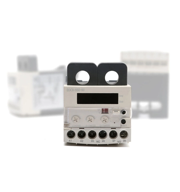
The relay block comprises the two protection units, phase protection unit and earth protection unit. When the value of the current in any of the phases is greater than the pick up value, the phase protecti.
[PDF]
Calculate and select the right number and spacing of cables for junction boxes using NEC guidelines to ensure safe, code-compliant electrical installations. Electrical clearances set the minimum safe distances for panels, overhead lines, pools, and buried wiring — and ignoring them has real consequences. 7* Class A and Class X circuits using physical conductors (e., metallic, optical fiber) shall be installed such that the outgoing and return conductors, exiting from and returning to the control unit, respectively, are routed separately. The outgoing and return (redundant) circuit conductors. Above finished grade or sidewalks, or from any platform or projection from which they might be reached. (If these areas are accessible to other than pedestrian traffic, then one of the other conditions applies). This step keeps your project safe and. In this guide, we'll break down everything you need to know to install a distribution box correctly and confidently. Choose the right box based on environment (indoor/outdoor), load capacity, and durability. Check for proper IP/NEMA ratings and material quality. Ensure safe placement: install in. When looking into electrical panel clearance safety, you need to start by looking at the requirements put in place by the national electric code, or NEC. The relevant section of the national electric code here is NEC 110. This set of code identifies how much clearance is needed around any type.
[PDF]
Phase A is yellow, Phase B is green, and Phase C is red DC Bus: positive red, negative blue Simulates the logo color of the busbar Voltage Unit (kV) - Color AC 0. 4 - Yellow-brown AC 3 - Dark Green AC 6 - Navy Blue AC 10 - Crimson AC 13. 8~20-Light green AC 35. The Inga–Shaba EHVDC Intertie (officially: The Inga–Shaba Extra High Voltage D. The following color codes apply to different AC and DC power systems: In some wiring systems, one phase has a higher voltage than the others, known as the high-leg. This. A 1,700 km power transmission link that transmits power from Inga Falls on the Congo River to the copper mining district of Katanga in the Democratic Republic of Congo (DRC). The Inga-Kolwezi link (formerly the Inga-Shaba link) was initially a ± 500 kV, 560 MW HVDC power transmission system. Image. Electrical wiring color codes are standardized systems used globally to identify the function and voltage of different wires in electrical installations, ensuring safety and efficiency in electrical work. These codes vary by region and application, with the National Electrical Code (NEC) and.
[PDF]
When you look at a fiber optic cable, the outer jacket color instantly tells you what type of fiber is inside. This color-coding system is standardized under TIA-598-C, making it easier for technicians and installers to identify cables at a glance. Understanding fiber‑optic color codes is essential for any technician tasked with installing, maintaining, or troubleshooting modern fiber networks. By adopting the TIA/EIA‑598C standard, you gain a universal “language” of colors that speeds identification, reduces miswiring, and enhances safety. Fiber optic color codes provide the essential identification framework that enables fiber technicians and network professionals to manage complex optical network installations efficiently. This guide explains how standardized fiber strands, cable jackets, connectors, and MPO systems simplify identification, prevent mismatches, and maintain signal integrity. Following industry. This guide explains the latest EIA/TIA-598-D fiber color-coding standard used to identify fiber types, inner fiber sequences, and connector polish styles.
[PDF]
Hello, in this tutorial we'll be using the TCS3200, TCS230 or GY-31, color sensor module with Arduino UNO board, and there will be project using a RGB LED to reproduce detected colors. When projects demand actual color recognition rather than simple light intensity measurements, basic photoresistors fall short. The TCS34725 Color Sensor Arduino pairing delivers true RGBC digital values with an integrated IR filter that produces measurements closely matching human color. It is a sophisticated module used to detect colors. It is highly precise and reliable in its work. Featuring an integrated photodiode array and RGB filters, it is highly accurate in measuring red, green, blue, and clear light components. An IR blocking filter, integrated on-chip and localized to the color sensing photodiodes, minimizes the IR spectral component of the incoming light and allows color measurements to be made. The TCS3200 is capable of detecting these colors accurately, making it an ideal tool for a range of industries including health, process control, and color sorting operations. At Regent Electronics, we offer high-quality TCS3200 color sensor modules that provide reliable performance for your DIY. The TCS3472 device provides a digital return of red, green, blue (RGB), and clear light sensing values. The module has an 8×8.
[PDF]
A2: According to EIA/TIA-598, the fiber optic cable color code defines the jacket color codes for different fiber types (SMF or MMF). Fiber optic color codes provide the essential identification framework that enables fiber technicians and network professionals to manage complex optical network installations efficiently. This standardized fiber optic color coding system helps prevent costly connection errors while dramatically. Understanding fiber‑optic color codes is essential for any technician tasked with installing, maintaining, or troubleshooting modern fiber networks. By adopting the TIA/EIA‑598C standard, you gain a universal “language” of colors that speeds identification, reduces miswiring, and enhances safety. The TIA-598-D standard defines a standardized color-coding system that engineers and technicians rely on to identify different types of fiber optic cables, connectors, and individual fibers. Designed for durability and reliability, the sleeves are constructed with an inner EVA meltable adhesive tube, and a polyolefin heat shrink outer tube. The strength member within the sleeve is made of. Color codes are used in fiber optics to identify fibers, cables and connectors. This coding system is the EIA/TIA-598 standard developed by the Electronic Industries Alliance (EIA) and the Telecommunications Industry.
[PDF]
Knowing when to use which color code can help you save time and prevent mistakes from occurring on the job. You'll likely need to use a tray cable with the E-1 color code if you're working on an electrical or utility application. When the project is n. Knowing when to use which color code can help you save time and prevent mistakes from occurring on the job. You'll likely need to use a tray cable with the E-1 color code if you're working on an electrical or utility application. When the project is not NEC-applicable, E-1 is OK to use. Locations where you'll likely encounter this color scheme incl. Based on the color combinations you see, you'll be able to determine what the wire is being used for. If you were to cut a cross-section of Kris-Tech wire and look at it head-on, you'd see a series of colored conductors arranged in a circle around the main conductor. Depending on which end of the cable you're looking at, you can read the colors clo. No matter the job type, rest assured there's a tray cable engineered to fit the job. Kris-Tech is ready for your next job with UL 1277 certified vinyl nylon tray cable (VNTC) and cross-linked polyethylene tray cable(XPTC). Whether you need some tray cable color-coded to meet NEC guidelines or want it custom-colored to match your preferences, Kris-T.
[PDF]
