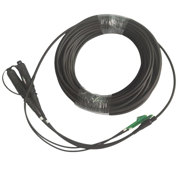
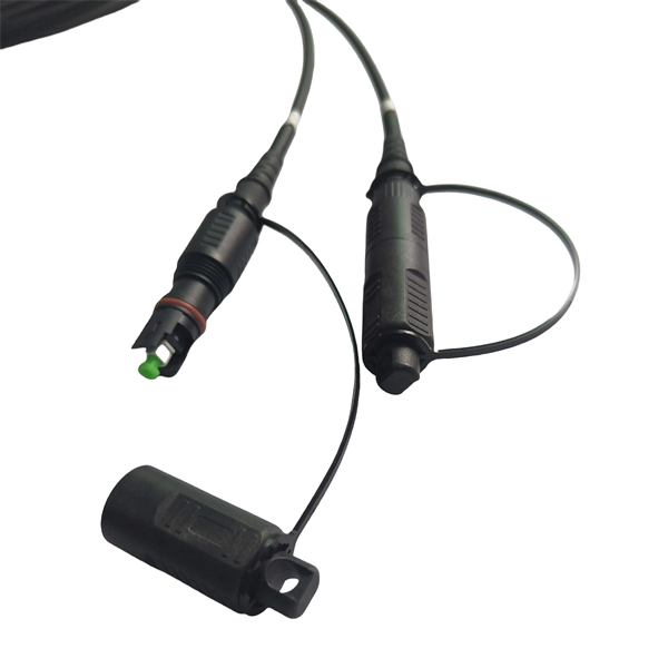
Learn the key difference between pigtail and jumper cables: only one end of a pigtail connects, while both ends of a jumper feature connectors. Similar to coaxial cable, but without mesh shielding, for jumper. When it comes to fiber optics, we naturally think of patch cords and pigtails. Usually people don't know the difference between the two. Let's find out together. Carrier-grade single-mode fiber patch. The Fiber Optic Patch Cord, also referred to as a fiber optic patch cable or fiber jumper, is a specialized cable designed for transmitting data signals using light waves in fiber optic communication systems. It is worth noting that fiber pigtails and patch cords are not the same concept. The main difference between fiber optic patch cords and fiber optic pigtails is that only one end of the fiber optic pigtail has an active connector, and both ends of. Jumper cables and portable jumper boxes are both tools used to revive a vehicle with a dead battery, but they have distinct differences despite sharing a similar end-goal. And with a plethora of purchasable options in both camps, it can be difficult to decide which way to spend your pretty pennies.
[PDF]
This article provides an in-depth exploration of OSFP copper cable technologies, including DAC, ACC, and AEC, with a focus on 400GB NDR splitter cable applications. Whether the signal is propagated by copper wire, optical fiber, Wi-Fi, or just yelling at the kids down the street, the signal is never as strong at the destination as it is at the source. In the case of physical voice communication, the kids will understand you if they are close-by. If they are. Insertion loss and attenuation are similar concepts, but one is assigned to a single component (insertion loss) whereas the other is assigned to generalized performance (attenuation). Both terms refer to a measurement comparing the signal strength received against a transmitted signal. Standard. Channel Master TV splitters are designed to equally divide the signals on the input port of the splitter to each of the output ports of the splitter. This. Insertion loss is the amount of energy that a signal loses as it travels along a cable link. It is a natural phenomenon that occurs for any type of transmission—whether it's electricity or data. This reduction of signal, also called attenuation, is directly related to the length of a cable—the. In fiber-optic networks like FTTx and PON, PLC splitters are key components for distributing optical signals to multiple users. However, each splitter has complex parameters, including insertion loss, return loss, polarization-dependent loss, and uniformity.
[PDF]
This comprehensive guide provides step-by-step instructions for sizing electrical cables in accordance with Australian Standard AS/NZS 3008. Electrolytic Tough Pitch (ETP) : The workhorse for most applications - 99. 9% pure with oxygen molecules peppered throughout the structure. Offers optimal balance of conductivity and cost Oxygen-Free Copper (OFC) : Created in oxygen-free environments, eliminating oxide impurities. Has marginally. Selecting the correct cable size is not just about electrical efficiency—it is a critical safety requirement. Under-sized cables lead to insulation failure, fire hazards, and significant equipment damage. Whether you're an electrical engineer, contractor, or student, this resource will help you master the essential calculations for selecting the. The National Electrical Code (NEC) provides clear guidelines for ground wire sizing through Table 250. 122, but understanding how to apply these requirements correctly can make the difference between a safe installation and a costly code violation. Proper grounding conductor sizing is critical for. Professional electrical wire sizing tool based on National Electrical Code (NEC) standards. Calculate proper wire gauge, voltage drop, and ampacity for safe electrical installations. Input your electrical parameters to get accurate wire size.
[PDF]
Mouser offers inventory, pricing, & datasheets for Copper Heat Sinks. Check each product page for other buying options. Need help? Copper heatsinks provide efficient heat transfer to keep your electronic components running at optimal temperatures. Discover the perfect cooling solution. Heat sinks are thermal management components designed to dissipate heat from high-power electronic devices and prevent overheating. Their core function is based on the principles of conduction, and convection, transferring heat from a heat source—such as a CPU, power transistor, or BGA package—to. Heat Sinks Cup Clips for TO-5 Case Style Semiconductors, 14. Heat Sinks Cup Clips for TO-5 Case Style Semiconductors, 14. A tariff of 10% may be applied if shipping to the United States. Due to copper's superior thermal conductivity (approximately 400 W/mK, nearly twice that of aluminum), copper heatsinks. Lot Of 2 Dell Copper Aluminum Heat Sink. Pulled From Clean Unit Sold As Scrap 100 PCS (8 Different Sizes) Heatsink Kit with Conductive Adhesive Tape, Alumi. Copper Aluminum Heat Sink Lot Sold As Scrap.
[PDF]
It is recommended to use tinned copper stranded wire with a minimum cross-sectional area of 4mm² for bridging, with tinned copper lugs crimped at both ends. Iron bolts welded at both ends of the cable troughs can rust and increase contact resistance. Cable tray may be used as the Equipment Grounding Conductor (EGC) in any installation where qualified persons will service the installed cable tray system. The metal in cable trays may be used as the EGC as per the limitations. Standard splice plates can often provide a safe electrical path if they are UL Classified and bolted tight. However, you must use copper bonding jumpers if the tray is painted or has expansion joints for movement. A. Cable tray wiring systems have excellent safety and dependability records. The intent of this article is to review grounding practices for cable tray. Snap Track Cable Tray Can be used as an Equipment Ground Conductor (EGC) Snap Track cable tray is UL Classified, marked with the available minimum cross sectional area and meets all requirements for use as an Equipment Ground Conductor per NEC Article 392. Standard Snap Track splices, tee's. What is best practice for terminating the ground wires within tray cable? Especially when you have a parallel tray cable feeder? For example: A parallel tray cable feeder is installed in cable tray to a 400 amp distribution panel.
[PDF]
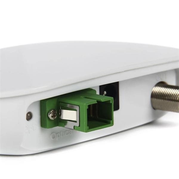
The optical fiber terminal box is usually placed at the end of the horizontal optical cable. The equipment connected by the optical jumper connected from the optical fiber terminal box through the coupler is the closest connection point to the terminal (switching. Some connectors commonly used in optical fiber connection in optical fiber links, such as: optical fiber distribution frame, terminal box, fiber distribution box, ODF distribution frame, what are the differences between them, let's take a look below. The functions of the four connectors can be. It is used in a terminal box to connect the optical fibers in the optical cable, and to connect the optical cable and the jumper through the terminal box coupler (adapter). Jumper Both ends of the jumper are movable connectors, which connect the pigtail and the device. Good quality fiber laying and termination systems help achieve minimal back reflection and low signal loss.
[PDF]
ShowMeCables offers a wide selection of LMR-600® thick low loss cables for long-distance runs. These LMR-600 cables are designed with flexibility, low loss and RF shielding with options such as ultra-flex, weatherproof and fire retardant rating for safe indoor, outdoor, or direct. TC-240-FM-X 3190-2891 <1. N Male Straight Plug 3. 35:1 (6) Hex/Knurl Solder Crimp A/G 1. Since 1975 delivering the world the best copper and copper alloy products to build a more connected, clean and efficient planet. is a Peruvian manufacturer that specializes in the design and production of electrical cables and conductors made from copper and aluminum for low and medium voltage applications. These. Check each product page for other buying options. Alligator Clips Electrical with Wires UL1015/18AWG, 6 Colors Jumper Test Leads Set, 1. Clips Soldered with Wires- EDGELEC Need help?. Our wire and cables have been helping real, hardworking pros on the job for more than 45 years. Their success is our success. Direct Wire is widely known as the market leader for highly durable and versatile cables and assemblies manufactured to stringent U. and international standards.
[PDF]
The key to choosing the appropriate one is to understand the theory on which each operates and the application that the attenuator will be applied to. Of course, you also need to be able to determine the attenuator value in decibels required for your application. Later in this article, we will discuss about the various advantages, disadvantages and application of attenuation. What is Attenuation? How Attenuation can be Prevented? What is Attenuation? Attenuation is a term in communication that refers to loss (reduction) in signal strength when a signal is. An optical attenuator, or fiber optic attenuator, is a device used to reduce the power level of an optical signal, either in free space or in an optical fiber. The basic types of optical attenuators are fixed, step-wise variable, and continuously variable. Optical attenuators are commonly used in. Fiber-optic attenuators are a specific type of optical attenuators which are used in fiber optics, e. for achieving a suitable signal level for a data receiver in a telecom system. Usually, such attenuators either have a housing equipped with some type of fiber connectors (e. The attenuator circuit will allow a known source of power to be reduced by a predetermined factor, which is usually expressed as decibels. Signal levels must be strong enough for data interpretation but not so strong as to damage the circuits in the receiver. Excessive fiber optic signal strength exceeding.
[PDF]
Use a spectrometer, which measures the amount of visible light that is absorbed by a solution, to test the purity of copper. The copper can remain in its solid form during testing and the spectrometer will not contaminate the sample. Conducting a copper quality test helps ensure that the material meets the purity standards required for optimal function across these critical applications: Electrical Applications: Nothing matches copper's ability to conduct electricity efficiently. Minor contaminants can severely impact its. The purity of copper is measured by what percentage of copper is found in the substance. The purest copper is over 99. Each technique's critical detection limits, selectivity, complexity, and. This chapter comprehensively evaluates recent advances in analytical methods for detecting copper, including atomic spectrometry, molecular spectrophotometry, electrochemical sensors, voltammetry, and chromatography. Each method will be broken down into easy-to-follow steps, ensuring you gain the confidence to perform these tests yourself. Ready to dive in and. The Copper industry encompasses a vast range of applications, from pure grades like OFE (Oxygen-Free Electronic), OFC (Oxygen-Free Copper), and ETP (Electrolytic Tough Pitch) to high-alloy compositions such as Brass and Cupro-Nickel. The elemental analysis of Copper, whether for purity or alloy.
[PDF]