In this guide, we will walk you through the process of setting up a network switch, from selecting the right equipment to connecting and testing the network. Ethernet switches, also called network switches, connect multiple devices via Ethernet cables. In contrast, a router connects your local area network (LAN) to the internet's. A practical, current guide to planning, pulling and terminating Cat6/Cat6A cable — tools, techniques, testing and labeling for reliable results. By Thomas McCormack • Updated Mar 17, 2026 • 12 min read • Lead Technician and Engineer, Data Wire Solutions Disclosure: Some links may be affiliate. With an Ethernet cable, you can hardwire your devices to your network, providing fast and efficient. Your ethernet switch doesn't come with any ethernet cables, so you want to have some on hand when setting up your switch. You'll need one cable to connect your ethernet switch and router together (assuming you want to provide your devices with an ethernet connection to the internet), and an. A network switch is a crucial component in any modern network, enabling seamless communication between devices. By the end of this tutorial. Connecting a network switch involves physically connecting devices using Ethernet cables and configuring them as needed, ultimately expanding your network connectivity and improving network performance. Connecting a network switch is a foundational skill for anyone managing a home or small business.
[PDF]
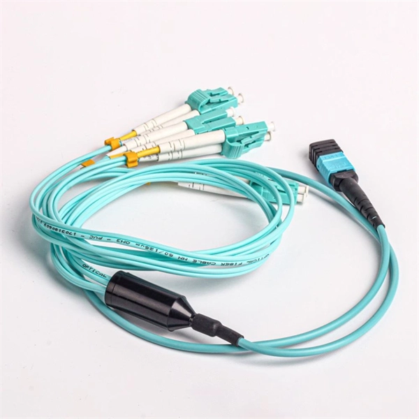
Dense Wavelength Division Multiplexing or DWDM is a technology which multiplexes or demultiplexes a number of optical carrier signals onto a single optical fiber by using different wavelengths (i. colors) of laser light. This chapter provides an overview of dense wavelength division multiplexing (DWDM) systems. This technique enables bidirectional communications over a. We produce fiber-coupled Wavelength-Division Multiplexing (WDM) devices that combine (Mux) or separate (DeMux) multiple wavelength channels into or from a single optical fiber. Two types are available: integrated arrayed waveguide gratings (AWG), offering low cost, compact size, and precise ITU. Wavelength division multiplexer (WDM) products are needed when a passive multiplexing or demultiplexing unit is required in a central office environment. WDMs are used in CATV headends and telephone company central offices. Read on to learn the fundamentals of this useful technology. This allows multiple channels of data to be transmitted simultaneously.
[PDF]
Two major factors should be considered: (1) the number of bits required to produce a statistically meaningful BER/BLER result, and (2) the baseband functionality required to verify coded BER/BLER. Bit Error Rate (BER) testing is a crucial aspect of evaluating the performance of digital communication systems. It involves measuring the rate at which errors occur in a transmitted bitstream compared to the expected bitstream at the receiver end. The BER measurement helps in assessing the quality. In digital transmission, the number of bit errors is the number of received bits of a data stream over a communication channel that have been altered due to noise, interference, distortion or bit synchronization errors. Adhering to strong layout practices ensures that the bit error rate is a random process rather than an indicator of design issues. The Bit Error Rate Analysis app is designed for analyzing BERs.
[PDF]
This application note explains how Site Master is used to measure cable insertion loss with different test methods and how to predict the maximum allowable cable insertion loss through manual calculations. Desktop Insertion Return Loss Tester with color screen has stable and reliable performance, which integrates stable light source, high-precision power meter, insertion loss meter and return loss meter into one multifunction instrument. Based on domestic customers'. Modern handheld analyzers, like the Keysight FieldFox Analysers, are designed specifically for cable and antenna testing (CAT), offering fast and accurate insertion loss testing across a wide frequency range. These tools are invaluable for both installation and maintenance, enabling field. Insertion loss is expressed in decibels or dB. The decibel is a logarithmic expression of the ratio of output voltage (voltage of the signal received at the end of the link) divided by input voltage (the voltage launched into the cable by the transmitter). 0 PCB transmission line losses in a PCB production environment. In wireless communication systems, the transmit and receive antennas are connected to the.
[PDF]