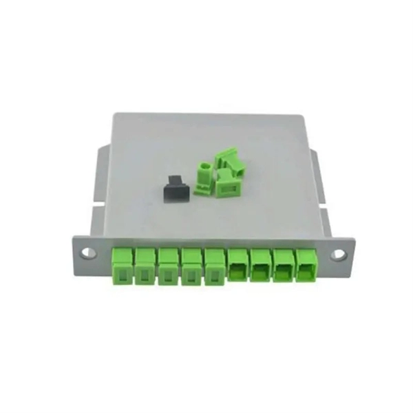
This AutoCAD DWG file includes a complete Single Line Diagram (SLD) of a Distribution Board, showing circuit breakers, wiring connections, and load distribution for lighting, power, and mechanical systems. An electrical panel box, also known as a breaker box or a distribution board, is a crucial component of any electrical system. It serves as a central hub for distributing electricity throughout a building, ensuring that power is delivered safely and efficiently to all the required locations. And all the switching and protective devices are installed in the. A distribution box is a key part of electrical systems in buildings. Inside, you'll find parts like circuit breakers and fuses that protect the system from problems like overloads and short circuits. Today, electrical systems are essential for homes and industries. Electrical Distribution board is used for controlling of utilization of power in the end point like as lighting circuit, power circuit and other equipment like as TV, fridge and airconditioning. The incomer supply is received from distribution panel. In this board, balance load is distributed as.
[PDF]
Download a comprehensive set of Cable Tray Installation CAD Blocks in DWG format, ideal for electrical engineers, MEP designers, and industrial layout planners. This article shares simple ways to plan your cable trays and wiring. We want to help electrical engineers, technicians, and anyone working with electrical setups build safe and good systems. This collection includes installation details for ladder trays, perforated trays, solid-bottom trays, and wire mesh trays, along with. This guide provides step-by-step instructions on installing a cable tray on a wall, covering different types of cable trays, tools needed, and safety tips. The Ladder Tray features light, rugged, tubular steel construction. It is designed for. In industrial settings, electrical and instrumentation (E&I) cable trays or bridge racks play a critical role in organizing and supporting power, control, and signal cables across facilities. An effective layout ensures safety, minimizes interference, reduces maintenance time, and keeps the overall. ALL TO BE CLEANED WITH A COMMERCIALLY AVAILABLE CLEANSER PRIOR TO ALL MARKERS AFFIXED PRIOR TO INSTALLATION OF ANY CABLE. BONDING JUMPER SHALL BE INSTALLED FOR ELECTRICAL CONTINUITY ACROSS ALL DETAIL AT INTERFACES AND/OR CONDUIT BUSHINGS SHALL INSTALLED FCR ENTRY OF CABLES.
[PDF]

One-line diagrams and detailed network data (lines, transformers, buses). Short-circuit models, including fault current calculations under various system configurations. Protective relay settings and coordination curves. Historical. presentation of protection and control relaying. The report will identify methodology behind these practices, present issues raised by the integration of microprocessor relays and the internal logic and external communication configurations, ying. Schematic diagrams of protection relays are essential tools for power engineers in the power generation, transmission, and distribution industry. This includes AC schematics and DC schematics and diagrams that prominently feature relaying. There are other equally important types of drawings that are not the subject. Power System Protective Relays: Principles & Practices Presenter: Rasheek Rifaat, P. Eng, IEEE Life Fellow IEEE/IAS/I&CPSD Protection & Coordination WG Chair Jacobs Canada, Calgary, AB rasheek. com IEEE Southern Alberta Section PES/IAS Joint Chapter Technical Seminar - November 2016. Recognized under 2(f) and 12 (B) of UGC ACT 1956 (Affiliated to JNTUH, Hyderabad, Approved by AICTE - Accredited by NBA & NAAC – 'A' Grade - ISO 9001:2015 Certified) Maisammaguda, Dhulapally (Post Via. Kompally), Secunderabad – 500100, Telangana State, India To introduce all kinds of circuit.
[PDF]
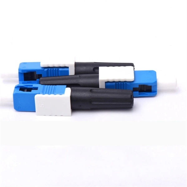
Ever wondered how pigtail bolts—critical components in power line fittings—are made? Watch as we take you through the entire manufacturing process step by st. How to Make Electrical Pigtails: This is a basic tutorial on what electrical pigtails are and how to make them. Disclaimer: Always use multiple sources and do your homework before performing any electrical work. Also, make sure all work is done within national and local code. Let's look at how to make pigtail wire links below. Also, it can join several wires to become a single conductor for electrical connections. Let us suppose I had 14 shielded wires to bring into a 15-pin connector where only one pin was available for shield grounds. Imagine how fat a lump there will be if all the shield terminations are located right next to. Bulb to Socket & Component to Connector Cross Reference Guide des spirales de raccord et des douilles Renvois ampoules/douilles et composants/connecteurs Guía de cables flexibles y adaptadores Referencias a bombillas/adaptadores y componentes/conectores NAPA®ECHLIN IGNITION, EMISSION, ENGINE. Pigtail connections are most frequently used to ground a switch or electrical outlet and for electrical devices that need to connect to multiple circuit wires. They also come in handy to lengthen circuit wires that are too short to reach a device. A pigtail is composed of three strands of wire.
[PDF]
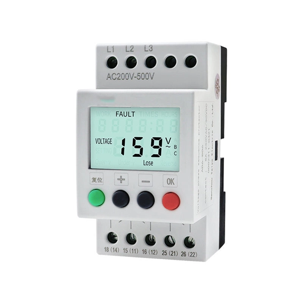
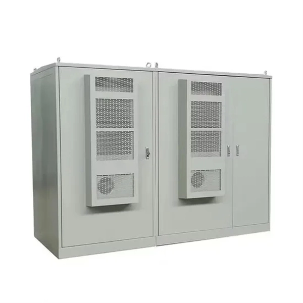
Simple 3-phase distribution board wiring diagram for home use, showing safe connection of power supply, breakers, neutral, and earth for residential electrical systems. Hey, in this article we are going to see the Three (3) Phase Distribution Board Wiring Diagram and Connection Procedure. The three-phase distribution board is used to distribute power to the three-phase loads and circuits such as three-phase motors, three-phase machinery, three-phase to. In a newly constructed residential area, a 10kV power line is introduced into the substation. After stepping down the voltage through the transformer's low-voltage side (0. The following is a detailed introduction about it: - **First-level Distribution. Utilities may have some control over and access to the energy stored in electric vehicles attached to the grid. ndards and conformity assessment activities in the United States. ANSI facilitates and promotes voluntary consensus standar rty or economic loss due to fire, electrical and related hazards. They deliver information and knowledge through more than 300 consensus codes and nspection to protect people.
[PDF]
In this video, we'll walk you through the process of wiring a home distribution box with a detailed connection diagram. Understanding the cable TV house wiring diagram can be helpful when troubleshooting connection issues or setting up new TV sets in your home. Whether you're an electrician or a DIY enthusiast, this guide will help you understand the basics of home electrical distribution. more Welcome to our channel! In this video. This course was adapted from the Department of Energy, Publication No. DOE-HDBK-1011/2-92, “Electrical Science”, Module 15, which is in the public domain. Gussow, Milton, Schaum's Outline Series. Distribution board is a safe system designed for house or building that included protective devices, isolator switches, circuit breaker and fuses to safely connect the cables and wires to the sub circuits and final sub circuits including their associated Live (Phase) Neutral and Earth conductors. Once this is identified, the wiring diagram should be drawn up, showing the main power line coming from the utility source and then branching off to the various branch circuits. This diagram should also indicate the type of circuit breaker used on each branch circuit. In addition to the main power.
[PDF]