Move and Change Shape: Ground shaking from an earthquake can make cable trays move and bend. This affects how stable they are and how much weight they can hold. This damages the whole cable tray. Cable tray and conduit systems have consistently performed well at conventional power and industrial facilities subjected to past strong-motion earthquakes larger than eastern U. plant safe shutdown earthquakes (1). This is so even though the systems are typically not designed for earthquake. The Pacific Earthquake Engineering Research (PEER) Centre has been developing a performance-based earthquake engineering (PBEE) methodology, which is based on explicit determination of performance, e., monetary losses, in a probabilistic manner where uncertainties in earthquake ground mo-tion. This appendix provides the design criteria for seismic Category I cable trays and their supports. Seismic Category II cable trays and their supports are also designed utilizing the design criteria of this appendix. They may be supported singly or there may be several pieces of onduit or buss ducts attached to a common trapeze. On some occasions the condui hanger rods 12 in or less in length be restrained. The 12 in length was determined based on the natural.
[PDF]
If a fault is detected, the relay will send signals to adjacent relays and circuit breakers, allowing the closest breaker to trip first while other breakers delay their operation. This selective coordination helps isolate the faulted zone while maintaining the power supply to the. A protection relay is a crucial component of electrical systems that safeguard infrastructure, employees, and equipment from electric problems and malfunctions. It functions as a watchdog by constantly surveying multiple system components including voltage, current, frequency, and phase angle. It. A protective relay is the vigilant guardian of electrical networks, constantly monitoring and analyzing electrical parameters to detect abnormal events. Acting as the first line of defence, it swiftly detects faults, such as short circuits or overcurrents. It triggers protective actions to isolate. In electrical engineering, a protective relay is a relay device designed to trip a circuit breaker when a fault is detected. : 4 The first protective relays were electromagnetic devices, relying on coils operating on moving parts to provide detection of abnormal operating conditions such as. A protective relay is an intelligent device that senses abnormal electrical conditions, such as overcurrent, under-voltage, or frequency deviations. It initiates the operation of circuit breakers to isolate the affected section.
[PDF]

A protection relay tripping circuit connects relays to breakers for fast fault isolation. Key components include trip/close coils and anti-pumping relays. Proper design, testing, and maintenance ensure reliable overcurrent, differential, and auto-reclosing protection in power. The protection relay tripping circuit refers to the critical electrical control loop that executes trip/close commands from protective relays to circuit breakers, ensuring rapid fault isolation in power systems. Essential. Electromechanical protective relays at a hydroelectric generating plant. The relays are in round glass cases. In electrical engineering, a protective relay is a relay device. A protective relay is an intelligent electrical device designed to detect faults in power systems and initiate corrective actions such as tripping a circuit breaker. Its main purpose is to safeguard electrical equipment like transformers, generators, and transmission lines from damage due to. By definition, a protective relay is a switchgear device that detects faults and initiates the circuit breaker operation to isolate the problematic component of the system. Electrical values are measured by these relays to determine abnormal circumferences of a circuit. It functions as a watchdog by constantly surveying multiple system components including voltage, current, frequency, and phase angle.
[PDF]
Thermal overload relays are widely used to protect motors. These devices work on the thermal effect principle. A thermal relay is an electromechanical device that detects temperature changes in electrical circuits, protecting equipment from overload and overheating. Thermal relays are critical components in electrical systems, designed to protect motors and other electrical equipment from damage caused by. Thermal Relay Definition: A thermal relay is defined as a device that uses the unequal expansion rates of metals in a bimetallic strip to detect overcurrent conditions. Working Principle: The thermal relay operates by heating a bimetallic strip, causing it to bend and close normally open contacts. So, the thermal relay is one of the types of the relay, used to provide complete safety against single phasing, unbalanced voltages & overloads. Thermal relays are the perfect solution for providing protection to motors which provides the most precise tripping for the electric motor during single. Introduction — The Core Device Protecting Industrial Motors Thermal overload relays are one of the most essential protection components in industrial motor circuits. Correct understanding and configuration ensure equipment safety and longevity. Its performance matches the actual heating characteristics of.
[PDF]
Single Line Drawing of the LV Distribution Network with feeder pillars and distribution boxes, showing cable length, size, voltage drop, and percentage voltage drop. All orders over MVR 300 qualify for free delivery, while orders under MVR 300 are subject to a MVR 50 delivery fee. In addition, we do delivery of goods up to Jetty/boat. In cases where the goods are requested to be delivered to a vessel, details. Let us help you with your questions and queries. Send a message to Viber: 7317894 Promotions, new products and sales. Directly to your inbox. If Datasheet includes multiple models, the model number should be highlighted Datasheet of Transmission equipment. Busbar configuration, dimensions, materials and rating. Single Line. © 2024 E-Talk Maldives. Nuomak is proud to announce a new cooperation with a client in the Maldives, for whom we have manufactured PS cabinets, MCCBs, and transparent waterproof electrical distribution boxes. These products are specially designed to meet the challenges of high humidity, salt spray, and harsh coastal. Can't find the product you need? Please give us feedback Dongfeng-covering various types of distribution boxes_rich and diverse product system, covering various types of distribution boxes and cabinet products.
[PDF]
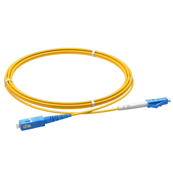
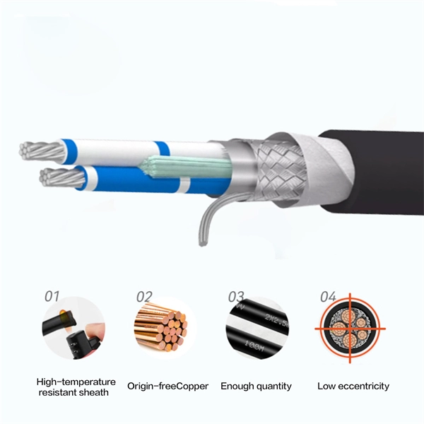
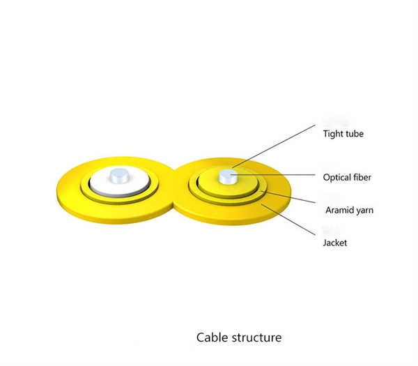
Temukan daftar Supplier, Pabrik, Importir, Distributor dan Toko Kabel Patch Cord untuk wilayah Indonesia . Update setiap hari, harga kompetitif dan layanan terpercaya. High performance and high quality connectors cable assembly are required for next generation optical networks to assure long term reliability for demanding applications such as FTTx, DWDM, 100G, CATV and etc. The connector assemblies are IEC, Telcordia and RoHS compliant. The termination passed. Prima Akses Digital Indonesia, is a Indonesian local company specialized in fiber optic product development and solution service for network infrastructure. Prima Akses Digital Indonesia, established in 2020, is supported by several partner companies and management which have been experienced in.
[PDF]
Browse enclosures designed for easy installation and cooling of enclosed equipment. Crafted from durable pre-galvanized steel, these boxes are designed to house wiring devices such as switches or outlets. With RACO's Switch Electrical Boxes, convenience is key. The device mounting holes are pre-tapped to. Power and Low Voltage Box For New Construction, Nail On. Low Voltage Side Provides Combination 1/2" and 3/4" Knockout. This intelligent fire emergency lighting system utilizes a centralized power controller distribution box, complying with the GB-17945-2010 standard, and provides over 90 minutes of emergency runtime. The system comprises an emergency lighting controller, a centralized power supply (EPS), and. Electrical Junction Box, Ventilated Design, Cable Grommets, Indoor/Outdoor Use with Mounting Panel & Hinged Cover. (Grey Cover, 13"x13"x5. 1") Need help? Streamline your home wiring and media setup with low voltage panel boxes. “Value After Rebate*” is the price or sale price minus the future rebate discounts. Valid on merchandise; excludes purchase of gift cards, rentals. For new construction and retrofit projects! Arlington's convenient combo box has power and low voltage openings in the same box, saving you time and money. LVD2, designed for new construction, comes with nails in place, ready for attachment to wood studs. Holes in the front flanges allow for screw.
[PDF]
LV overhead lines are protected against overcurrents using fuses or circuit breakers. Protection of MV overhead lines is usually achieved by overcurrent relays (50; 50N; 51; 51N; 67; 67N) connected to.
[PDF]

With its novel and future-oriented approach our software solution for system-based protection testing, performs tests independent of relay type, relay manufacturer, and offers extensive parameter settings. It focuses on. With its novel and future-oriented approach our software solution for system-based protection testing, performs tests independent of relay type, relay manufacturer, and offers extensive parameter settings. It focuses on the correct behavior of the protection system by simulating realistic events in the power system. RelaySimTest. Specifically designed for settings-based protection testing with a high degree of automation, our modular software Test Universe offers numerous functions and application-optimized test modules that save you valuable time. Test Universe. Use CMControl P for quick and easy manual testing. CMControl P is available as an App for Android tablets and Windows PC, or as a dedicated front-end device. CMControl P. With this software the CMC test set becomes a multifunctional measurement and recording unit. You can use EnerLyzer in parallel with the software used for operating your CMC. Enerlyzer. The open programming interface CMEngine enables you to integrate the CMC test sets into your own testing environment and control them within any type of application. CMEngine.
[PDF]

In this guide, we'll explore what protection relays are, how they're classified, the types available, and how they work with instrument transformers to create secure zones of protection. What Is a Protection Relay?. Protective Relay Definition: A protective relay is an automatic device that senses abnormal conditions in electrical circuits and triggers actions to isolate faults. Types of Protective Relays: Protective relays are categorized by their mechanism (electromagnetic, static, mechanical) and function. This article covers various types of protective relays, such as overcurrent, directional, and differential relays, highlighting their operating characteristics and applications in electrical systems. They don't just protect equipment; they ensure safety, prevent downtime, and save lives. A protective relay is a device that detects the fault and initiates the operation of the circuit breaker to isolate the defective element from the rest of the. The rectangular devices are test connection blocks, used for testing and isolation of instrument transformer circuits.
[PDF]
Every protection system which isolates a faulty element is required to satisfy four basic requirements: (i) reliability; (ii) selectively; (iii) sensitivity; and (iv) speed of operation. Protection system is an extremely important part of the power system as it is provided to operate under abnormal conditions to prevent failure or isolate trouble and limit its effect. It is designed to detect and isolate faults or abnormal conditions within the system to prevent damage, minimize downtime, and maintain power quality. This. Relay protection primarily operates on the principle of utilizing the variations in electrical quantities (such as current, voltage, power, frequency, etc. It emphasizes selectivity, coordination, fault response, and system behavior rather than individual relay devices. Relay protection is often misunderstood as a. Protective relays and devices have been developed over 100 years ago to provide “lastline”of defense for the electrical systems. They are intended to quickly identify a fault and isolate it so the balance of the system continue to run under normal conditions. The selection and applications of. Abstract: Information on the concepts of protection of ac transmission lines is presented in this guide. Many important issues, such as coordination of settings, operating times, characteristics of.
[PDF]
In the ring distribution network, differential relays, which rely on communication between the protection relays, are used for the underground cable protection. To guarantee cable protection when communication is failed, an auxiliary protection by using directional overcurrent. The use of ring circuits in 6 – 35 kV distributed electrical networks can improve the reliability of power supply. An increase in the load power and the share of distributed generation and renewable energy sources causes the redistribution of the power flow during the operation of an electrical. The selected protection principle affects the operating speed of the protection, which has a significant im-pact on the harm caused by short circuits. The faster the protection operates, the smaller the resulting ha-zards, damage and the thermal stress will be. Further, the duration of the voltage. ABSTRACT: Over current protection is the simplest form of power system protection of distribution line. In. The purpose of this study is to investigate the coordination of overcurrent relay in different types of the distribution network, which are radial, ring, and interconnected distribution system during line to ground fault occurrence at the bus. Usually, this refers to medium-voltage networks, since they are protected by numerical relay devices, as opposed to low-voltage networks, where utility operators allocate.
[PDF]

One-line diagrams and detailed network data (lines, transformers, buses). Short-circuit models, including fault current calculations under various system configurations. Protective relay settings and coordination curves. Historical. presentation of protection and control relaying. The report will identify methodology behind these practices, present issues raised by the integration of microprocessor relays and the internal logic and external communication configurations, ying. Schematic diagrams of protection relays are essential tools for power engineers in the power generation, transmission, and distribution industry. This includes AC schematics and DC schematics and diagrams that prominently feature relaying. There are other equally important types of drawings that are not the subject. Power System Protective Relays: Principles & Practices Presenter: Rasheek Rifaat, P. Eng, IEEE Life Fellow IEEE/IAS/I&CPSD Protection & Coordination WG Chair Jacobs Canada, Calgary, AB rasheek. com IEEE Southern Alberta Section PES/IAS Joint Chapter Technical Seminar - November 2016. Recognized under 2(f) and 12 (B) of UGC ACT 1956 (Affiliated to JNTUH, Hyderabad, Approved by AICTE - Accredited by NBA & NAAC – 'A' Grade - ISO 9001:2015 Certified) Maisammaguda, Dhulapally (Post Via. Kompally), Secunderabad – 500100, Telangana State, India To introduce all kinds of circuit.
[PDF]
Protection: CVTs supply voltage signals to protective relays, enabling them to detect faults and initiate appropriate actions, such as circuit breaker tripping. Control: CVTs can also be used in control systems to monitor voltage levels and provide feedback for voltage regulation. Capacitive Voltage Transformers (CVTs) are common in high-vo tage transmission line applications. These same applications require fast, yet secure protection. However, as the requirement for faster protective relays grows T models whose purpose is to identify which major CVT components contribute. ve Voltage (CVT) and Capacitance Coupled Voltage Transformers (CCVT). With this comprehensive range of accurate power sensing devices coupled with GE's vertical integration approach and skilled design engineering staf, we work closely with our globa ems for applications ranging from high-voltage to. Capacitive Voltage Transformers (CVTs), also known as capacitor voltage transformers, are essential components in high-voltage power systems. They provide a cost-effective and reliable means of measuring voltage and supplying power to protective relays and metering equipment. This essay will delve. Potential transformers and coupling capacitor voltage transformers (CCVT's) have been used successfully for providing voltage to the inputs of meters and relays since the 1960's. It utilizes a capacitive voltage divider in conjunction with an electromagnetic voltage converter to provide a.
[PDF]
The relay block comprises the two protection units, phase protection unit and earth protection unit. When the value of the current in any of the phases is greater than the pick up value, the phase protecti.
[PDF]