Cable Trays* — Max two 24 in. (610 mm) wide by max 6 in. (151 mm) deep open-ladder cable tray with channel-shaped side rails formed of 0. 54 mm) thick aluminum or min 0. In practice, cable tray dimensions are a system of interrelated measurements —width, depth, length, and material thickness—that directly affect cable fill compliance, heat dissipation, structural loading, and long-term expandability. From an engineering standpoint, cable tray dimensions are not. SS304, and SS316. The annular space between the cable trays shall be min 2 in. Wire Mesh tray is generally used for telecommunication and fiber optic applications and are installed on short support spans, 4 to 8 feet Other sizes be produced according to customer's drawing. ♦ Electro zinc plated–for indoor use to BS EN 12329-2000, 12microns thick. ♦ Hot Dipped Galvanized–for. us-trations without notice. All illustrations, descriptions and technical information included in this document are provided as indications and can cable trays are equivalent. The mechanical and electrical characteristics, tests, certifications, overall quality management, recommendations mentioned. NOTICE AND DISCLAIMER (NEMA) The information in this publication was considered technically sound by a consensus among persons engaged in its development at the time it was approved. Consensus does not necessarily mean there was unanimous agreement among every person participating in the.
[PDF]
Create NEC-compliant electrical load calculations with our free tool. Get accurate results with PDF outputs and automatic square footage detection. This electrical panel load calculator starts with the capacity question: a 200A, 120/240V panel reaches the practical 80% planning threshold at 160A, so new continuous additions get tight when the calculated load is already near that point. In the modeled all-electric home example, the panel. Free electrical load calculation tool for residential and commercial buildings. Calculate service entrance sizing, panel loads, demand factors, and ensure NEC Article 220 compliance. Proper load calculations ensure that electrical systems are safely designed with adequate capacity for present and future needs. Electrical capacity is the maximum amount of electricity a circuit, breaker box or overall residential system can safely withstand. The outside power box serves as a crucial junction where power is distributed to various circuits. This distribution network is vital. Use our free tool to get accurate results with an instant PDF report that helps finish inspections and close customers faster.
[PDF]
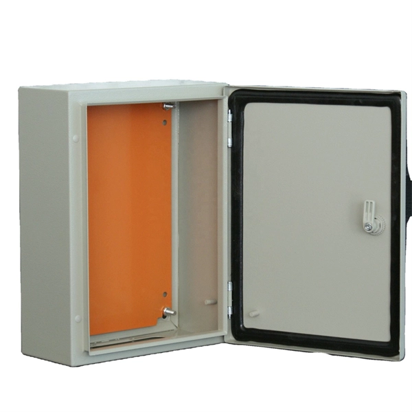
Design requirements for low voltage distribution boxes cover NEC, IEC, and safety standards to ensure reliable, compliant electrical installations. You must make safety your top priority when working with low voltage distribution boxes. Among the most widely recognized frameworks governing electrical panel design are the IEC (International Electrotechnical Commission) standards, particularly the IEC 61439 series, which defines the requirements for low-voltage switchgear and controlgear assemblies. In this blog, we explore the. Standards are for reference only. All new extension or modifications require an approved design and a preconstruction meeting with EWEB prior to installation. Need more information on how to get a design? Contact us at distributionengineering@eweb. NEC Article 408 covers switchboards, switchgear, and Panelboards installation and applications. Redesigned to improve safety, product longevity and appearance over time. Note: Eaton recommends mounting redesigned enclosures with at least six inches of clearance between adjacent structures to provide adequate access to side bolts. a Applicable for type LWPQ only. A distribution box is the heart of any electrical system. It takes the incoming power and safely distributes it to different circuits throughout your building. Whether in a home or an industrial facility, this box keeps.
[PDF]
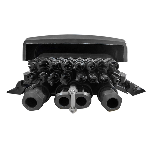
As shown in the figure below, the main cable consists of three conductor wires extending from the top of the motor flat lead extension to the wellhead banded to the production tubing. The ESP cable carries current (amperage) from the motor controller at the surface down to the motor. CAVALCADE™ ESP power cable meets the high-quality standards required for any oil and gas industry specification–even the most challenging unconventional applications–to deliver the electrical requirements of your ESP and to extend system run life. Get cable built with solid copper conductors. Typically, it is banded or clamped to the production tubing from below the wellhead to the ESP unit because it is not designed to support its own weight. It is a specially constructed three-phase power. Levare is one of few artificial lift equipment providers manufacturing the complete ESP system including power cable. The total facilities capacity is approximately 10,000 kilometers (over 6,200 miles) of power and motor lead extension (MLE) cables annually. It is a specially constructed three-phase power cable designed. When performing well interventions, the choice of a suitable cable is critical to ensure well control is maintained while deploying wireline through pressure control equipment (PCE). Depending on the well conditions, many considerations should be taken into account for choosing the best cable.
[PDF]