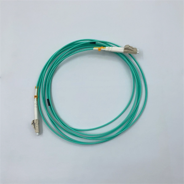
This video shows 2D wave simulations of optical fibers and presents differences between single-mode and multi-mode light propagation. more Audio tracks for some languages were automatically generated. Learn more. This applet is called FIMOC (fiber-optic mode online calculator). With it you will be able to calculate and visualize the propagating modes of any step-index fiber of your choice. If you want to go directly to the software, scroll to the bottom, but if you are interested in where these modes come. Optical fiber sensors have attracted significant interest in the sensing field. This paper presents a C-shaped optical fiber sensor sensitivity enhancement through design. RP Fiber Power is a powerful software for simulation, design and optimization of fiber devices — in particular, fiber amplifiers and lasers as well as other types of waveguide lasers (and even many bulk lasers), but also fiber couplers, multi-core fibers, helical core fibers, tapered fibers and. In this proposed workflow, we couple Ansys Mechanical TM with Ansys Lumerical TM, creating an innovative workflow that can detect the position of a random mechanical strain along an optical fiber. In this proposed workflow, DFOS utilizes standard single mode optical fiber as a sensing element. 1Department of Mechanical and Aerospace Engineering, University of Texas at Arlington, 500 W.
[PDF]
In fiber-optic communications, wavelength-division multiplexing (WDM) is a technology which multiplexes a number of optical carrier signals onto a single optical fiber by using different wavelengths (i.e., colors) of laser light. This technique enables bidirectional communications over a single strand of fiber (also called wavelength-division duplexing) as well as multiplication of capacity. The. SystemsA WDM system uses a at the to join the several signals together and a at the to split them apart. With the right type of fiber, it is possible to have a device that does both s. Originally, the term coarse wavelength-division multiplexing (CWDM) was fairly generic and described a number of different channel configurations. In general, the choice of channel spacings and frequency in these co.
[PDF]
Welcome to our light sources category, where we offer advanced calibration solutions designed for precision and accuracy in scientific measurements. Our selection encompasses two primary subcategories: “Wavelength Calibration” and “Radiometric Calibration,” featuring state-of-the-art products. This. As a result of a 2-year research project, finalised in 2020, GL Optic developed new calibration facilities and created Calibration and Research Laboratory of Optical Radiation ( CARLO ). Today, CARLO is the only laboratory in Central and Eastern Europe equipped with the Black Body Radiator – the. We offer two types of light sources for calibration: Pen-Ray line sources for the wavelength calibration of spectroscopic instruments and calibrated irradiance sources covering UV-NIR. All Avantes spectrometers are factory wavelength calibrated and do not require recalibration as they have fixed slits and optics. Options include mercury-argon (253-1700 nm), krypton (427-893 nm), neon (540-754 nm), argon (696-1704 nm) and xenon (916-1984 nm) gas-discharge emission sources. Multiple LED sources can be efficiently combined into a single output beam, and offer major advantages such as long life-time, easily tunable spectrum, high power stability, and ultra-fast switching (on the microseconds level) without using moving mechanical components. Multi-Wavelength Collimated.
[PDF]
Light decay in light divisions refers to the decrease in light intensity as it travels through optical fibers or other transmission media. This decay can occur due to a number of factors, including absorption, scattering, and reflection. If you don't know what kind of losses to expect in your system, you won't know how many other components. It is also known as fiber loss or signal loss. The signal attenuation of fiber determines the maximum distance between transmitter and receiver. Another important property of optical fiber is. Fiber loss, also called fiber optic attenuation or attenuation loss, refers to the loss of signal between input and output. Losses can be introduced by various means such as intrinsic material absorption, scattering, bending, connector loss and more. This loss can significantly reduce the effectiveness of optical fibers in applications such as telecommunications, imaging systems, and even simple fiber-optic tools like flashlights. In the early days of.
[PDF]
The worker must then connect one end of the fiber optic cable to a light source. Then, once they have done this they will turn on the light source and press the button on the. When it comes to testing fiber optic cables, a Visual Fault Locator (VFL) is an essential tool in your toolkit. A VFL is used to detect faults, breaks, or bends in fiber optic cables by emitting a bright red light that is visible even through the fiber's jacket. It's a cost-effective and. How to use fiber optic red light pen? It can be seen from the above that the red light pen has many uses, but its most common use is to detect the connectivity of the optical fiber and locate the fault point of the optical fiber. more How to use a VFL to identify a fiber optic cable from end to end. Viavi VFL:https://amzn. to/3L7cL6RTools I use:3 Hole Strippershttps://amzn. Within the pen, a small but powerful laser sends out an intense red light. Here is how the pen helps detect errors. If the fiber optic cable is appropriately intact and. The RPEN-210 is a necessity tool that should not be missing from any fiber plant manager or fiber optic installing technician. The Visual Fault Locator (VFL) Pen has a visible red light source centered on 650nm. Tool sends visible light over a fiber strand with a 10mW power, good enough to reach.
[PDF]
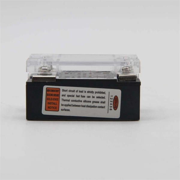
Check the electrical load and ensure that the sensors do not exceed the 10 Amp maximum. Check each wire for damage that may lead to a short. Check the following: Check if all cable connections are tightened with a torque moment of 14Nm (17Nm for the M10 model). Check if the surface area. Channel has NO voltage and there is an active fault. Check for tripped or missing circuit breaker Sticky fault on the channel. Sticky Fault - an indicator that a fault has occurred that will stay until the indicator has been cleared manually. Channel has NO. Each powernet distribution box (PNDB) on the vehicle provides up to 4 low amperage circuits (30 amp and less), and up to three high amperage circuits through midi fuses. The fuses are located behind a cover on the face of the PNDB. On vehicles equipped with a cab load disconnect switch (CLDS), the. I have the following issues, green light on shunt all red lights on distributor, no SOC on screen. Everything else is working great. In troubleshooting I removed all the fuses from the distributor just to see if the fuse lights would not illuminate red and get green power. Any. Show the control box indicator lights. Show the accessory response (or lack of response). For LED Light Kit issues, also provide a photo of the LED Y-cable (to confirm which version you have). Videos and photos are required to file warranty claims with the manufacturer.
[PDF]
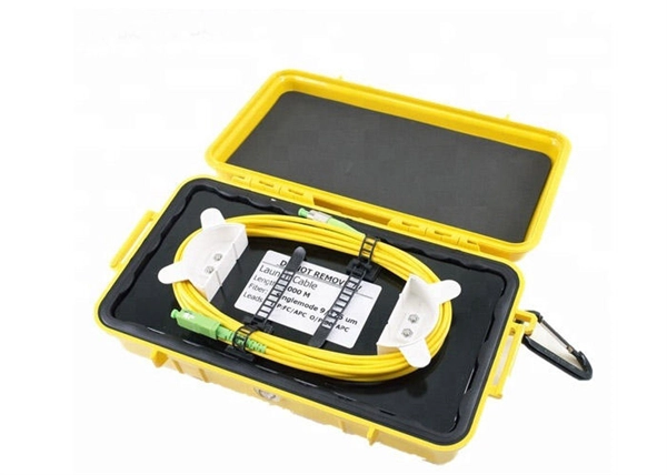
Singlemode fiber features a small core diameter of just 9 µm and allows only one mode of light to propagate. This design minimizes signal loss and supports high-bandwidth applications over long distances. 5 µm) with multiple light. Single-mode fibers (also called monomode fibers) are optical fibers which are designed such that they support only a single propagation mode (LP 01) per polarization direction for a given wavelength. Higher-order modes like LP 11, LP 20 etc. It allows just one light signal – typically lasers – to pass through at a time. This keeps the signal tight and strong, making it ideal for long. Optical Fiber comes in two main categories: singlemode and multimode. Singlemode fiber is designed for long-distance data transmission, typically over distances greater than 10 kilometers. Glass or plastic are often used to make these fibers. Metal wires are used in optical fibers because they protect against damage and are immune to electromagnetic interference. This characteristic allows for significantly less signal degradation and higher data rates over.
[PDF]
When the LOS light turns red or blinks red, it usually means your ONT or fiber router is not receiving the optical signal properly from the network. In most cases, this is not just a normal WiFi issue. It usually points to a signal-side or line-side problem rather than a small. The LOS light on your router indicates the status of your internet connection to the Internet Service Provider (ISP). When it's green and steady, everything is fine. Fortunately, diagnosing and resolving these issues doesn't have to be complicated. In this comprehensive guide, we will walk you. Whether your modem is blinking orange, your router has a solid red light, or you are staring at a mysterious "DS" indicator, you will find the answer below. A solid green or white light on your modem or router almost always means everything is working normally. You might feel like you're staring into the abyss of digital darkness, wondering what went wrong. Before you panic or call tech support, there are several simple fixes you can try at home that often solve this problem in minutes. Existing Krishii Fiber customers can share their registered mobile number, area and a.
[PDF]
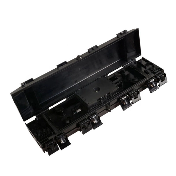
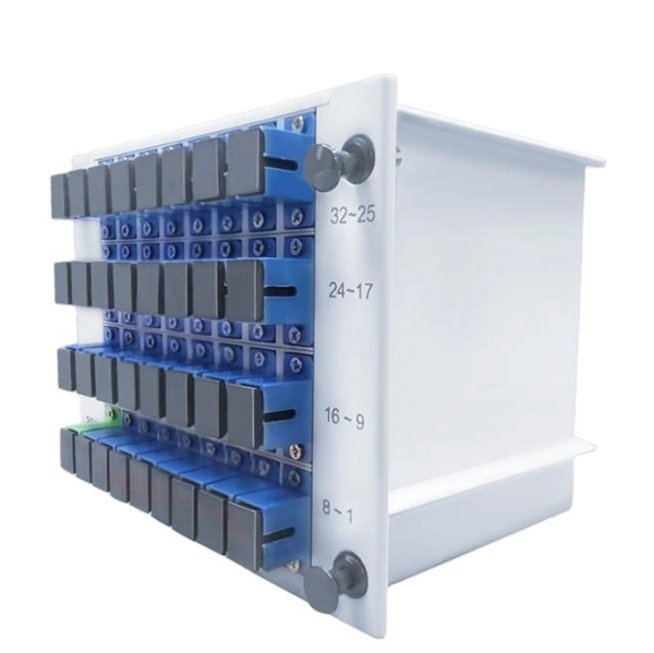
Find reliable optical fiber distribution frame prices for various needs. Shop high-quality, durable ODFs and patch panels for efficient communication networks. Understanding the landscape of main distribution frame (MDF) pricing is crucial for network architects and procurement professionals. The market is dynamic, influenced by technological upgrades and shifting demand across industries. Strategic purchasing requires a clear view of these forces. Pre-terminated ODFs with cables are pre-installed with connectors and cable for quick and easy installation. Units with pre-terminated cables offer. Fiber distribution box is suitable for the wiring connection of optical cable and optical communication equipment, through the adapter in the wiring box, the optical jumper leads the optical signal, and realizes the optical wiring function. OTRANS strives to provide you with professional, reliable. Max. Capacity: Company Info. Capacity Once receive your question, the supplier will answer you as soon as possible. Enter between 20 to 4,000 characters. The fibre optic distribution frame is a high-capacity fibre distribution frame designed for fibre termination, cross connection, and distribution in optical access networks. It enables efficient connection, routing, and management. HIGH DENSITY FLOOR STANDING. This fiber optic distribution.
[PDF]
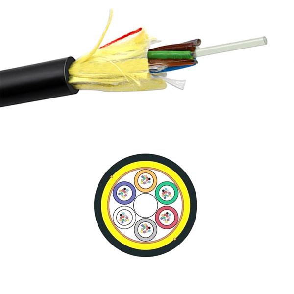
Rugged Construction: Impact test rated IK10, with a pull force of 100N. Odolné materiály: All stainless steel plates and anti-rusting bolts/nuts. Bend Radius Control: Maintains fiber bend radius over 40mm. Versatile Use: Suitable for fusion splicing. The CIos-8A-192 fiber optic splice closure can accommodate up to 192 splicing points as an outdoor closure. It serves as a splicing point for feeder cables to connect with distribution cables in FTTx backbone network systems. This closure integrates fiber splicing, storage, and cable management. This FOA Technical Bulletin describes recommended procedures for installing and testing cabling networks that use fiber optic cables and related components to carry signals for communications, security, control and similar purposes. This closure integrates fiber splicing, storage, and cable management. For LED lights, IK08 is often enough for normal commercial spaces, IK09 fits tougher industrial or outdoor areas, and IK10 is preferred where vandalism, sports impacts, loading docks, or hazardous-location abuse are realistic risks. It sounds medieval, but it's actually sophisticated engineering! The test apparatus includes pendulum hammers or steel spheres of different weights (from 0. 25 kg to 5 kg) that strike the device with precisely.
[PDF]
Resolving these issues involves steps like checking cable connections, soft resets, updating firmware, and specific solutions for different router brands like ASUS and Spectrum. It often indicates that something is wrong with your internet connection or the device itself. Fortunately, diagnosing and resolving these issues doesn't have to be complicated. In this comprehensive guide, we will walk you through the common causes of a red light on your router and provide. A router showing a red light can mean different things, like a service outage, misconfiguration, or loose connection, all of which can lead to a broken internet connection. Fortunately, there are heaps of ways to fix a red blinking light on your router. One of the first things you should try is to. Turn off the router and disconnect the power cord. Check that the PON cable is free from damage or sprains. Even if you have the best router, you may experience a loss of connection or other issues and see that dreaded red light. When it's green and steady, everything is fine. However, when it blinks red or stays solid red, it signifies a Loss of Signal, a problem preventing your router from communicating.
[PDF]
Los sensores de luz presentan una variedad de dimensiones, desde modelos compactos ideales para aplicaciones domésticas hasta sensores más grandes diseñados para entornos industriales. Estas dim.
[PDF]