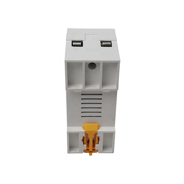
Calculate and select the right number and spacing of cables for junction boxes using NEC guidelines to ensure safe, code-compliant electrical installations. Electrical clearances set the minimum safe distances for panels, overhead lines, pools, and buried wiring — and ignoring them has real consequences. 7* Class A and Class X circuits using physical conductors (e., metallic, optical fiber) shall be installed such that the outgoing and return conductors, exiting from and returning to the control unit, respectively, are routed separately. The outgoing and return (redundant) circuit conductors. Above finished grade or sidewalks, or from any platform or projection from which they might be reached. (If these areas are accessible to other than pedestrian traffic, then one of the other conditions applies). This step keeps your project safe and. In this guide, we'll break down everything you need to know to install a distribution box correctly and confidently. Choose the right box based on environment (indoor/outdoor), load capacity, and durability. Check for proper IP/NEMA ratings and material quality. Ensure safe placement: install in. When looking into electrical panel clearance safety, you need to start by looking at the requirements put in place by the national electric code, or NEC. The relevant section of the national electric code here is NEC 110. This set of code identifies how much clearance is needed around any type.
[PDF]
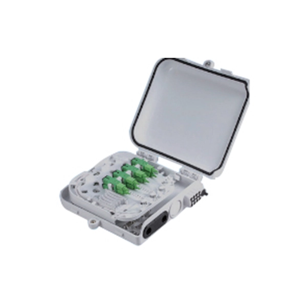
Need some clarification about NEC 770. 47 (B), it says that the direct buried conductive fiber optic cable shall be 12 in (300 mm) away from the power cables. Separating high-voltage power cables from low-voltage communication cables is a fundamental requirement in any electrical installation. This practice is mandatory for two distinct reasons: ensuring the safety of the structure and its occupants, and preserving the integrity of sensitive data. Maintaining proper separation between power, data, and limited energy cabling is foundational to system performance, safety, and code compliance. Separation isn't just an EMI precaution — it protects signaling, reduces rework, and ensures pathways meet inspection expectations across risers. TECHNICAL GUIDELINE July 30, 2020 TG030 Rev. 4 Pathway Separation Between Telecommunication Cables and Power Cables Communications cables are, by design or necessity, often installed in close proximity and/or in the same pathway as power service cables. The electrical energy of the power cables can. This standard titled “Commercial Building Standard for Telecommunications Pathways and Spaces” is a joint publication of ANSI/TIA/EIA. Its current version (ANSI/TIA/EIA/-569-B) was published in October 1, 2004 and describes EMI aspects in Article 10. ca with numerous contributions by others. "UTP Separation Guidelines From EMI Sources". The values are the same as the cabling pathways standard, EIA-569, table 4.
[PDF]
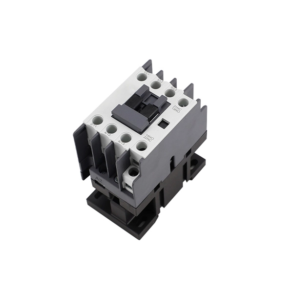
The relay block comprises the two protection units, phase protection unit and earth protection unit. When the value of the current in any of the phases is greater than the pick up value, the phase protecti.
[PDF]
Patch cords, also known as jumper cables or fiber optic jumpers, are short lengths of fiber optic cable used to connect devices within a fiber optic network. They play a crucial role in establishing reliable and high-speed data transmission between equipment such as switches . The fiber optic patch cable must, therefore, be carefully considered. Behind its slender appearance lies the fusion of core types, connector types, and polish levels, each chosen for a specific application. Choosing the right cable thus boils down to educating oneself about fiber optic patch cable. As networks move to higher speeds and higher density, choosing the right fiber optic patch cords becomes critical to the reliability of your system. At ZION Communication, we design and manufacture a full range of fiber patch cords for: This guide will help you quickly understand the main types of. These short fiber optic cords connect transceivers, switches, patch panels, and servers. Without them, even the best optical modules and switches cannot deliver performance. In today's high-speed data transmission era, fiber optic patch cords have become essential components in telecommunication networks, data centers, and enterprise cabling systems.
[PDF]
In telecommunications, an eye pattern, also known as an eye diagram, is an oscilloscope display in which a digital signal from a receiver is repetitively sampled and applied to the vertical input (y-axis), while the data rate is used to trigger the horizontal sweep (x-axis). It is so called because, for several types of coding, the pattern looks like a series of eyes between a pair of rails. It is a too. CalculationThe first step of computing an eye pattern is normally to obtain the waveform being analyzed in a quantized form. This may be done by measuring an actual electrical system with an oscilloscope of sufficient bandwidth,. Each form of baseband modulation produces an eye pattern with a unique appearance. The eye pattern of a signal should consist of two clearly distinct levels with smooth tra. Many properties of a can be seen in the eye pattern. applied to a signal produces an additional level for each value of the signal, which is higher (for pre-emphasis) or lower (for de-emp.
[PDF]
