
One-line diagrams and detailed network data (lines, transformers, buses). Short-circuit models, including fault current calculations under various system configurations. Protective relay settings and coordination curves. Historical. presentation of protection and control relaying. The report will identify methodology behind these practices, present issues raised by the integration of microprocessor relays and the internal logic and external communication configurations, ying. Schematic diagrams of protection relays are essential tools for power engineers in the power generation, transmission, and distribution industry. This includes AC schematics and DC schematics and diagrams that prominently feature relaying. There are other equally important types of drawings that are not the subject. Power System Protective Relays: Principles & Practices Presenter: Rasheek Rifaat, P. Eng, IEEE Life Fellow IEEE/IAS/I&CPSD Protection & Coordination WG Chair Jacobs Canada, Calgary, AB rasheek. com IEEE Southern Alberta Section PES/IAS Joint Chapter Technical Seminar - November 2016. Recognized under 2(f) and 12 (B) of UGC ACT 1956 (Affiliated to JNTUH, Hyderabad, Approved by AICTE - Accredited by NBA & NAAC – 'A' Grade - ISO 9001:2015 Certified) Maisammaguda, Dhulapally (Post Via. Kompally), Secunderabad – 500100, Telangana State, India To introduce all kinds of circuit.
[PDF]
In telecommunications, an eye pattern, also known as an eye diagram, is an oscilloscope display in which a digital signal from a receiver is repetitively sampled and applied to the vertical input (y-axis), while the data rate is used to trigger the horizontal sweep (x-axis). It is so called because, for several types of coding, the pattern looks like a series of eyes between a pair of rails. It is a too. CalculationThe first step of computing an eye pattern is normally to obtain the waveform being analyzed in a quantized form. This may be done by measuring an actual electrical system with an oscilloscope of sufficient bandwidth,. Each form of baseband modulation produces an eye pattern with a unique appearance. The eye pattern of a signal should consist of two clearly distinct levels with smooth tra. Many properties of a can be seen in the eye pattern. applied to a signal produces an additional level for each value of the signal, which is higher (for pre-emphasis) or lower (for de-emp.
[PDF]
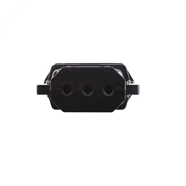
This AutoCAD DWG file includes a complete Single Line Diagram (SLD) of a Distribution Board, showing circuit breakers, wiring connections, and load distribution for lighting, power, and mechanical systems. An electrical panel box, also known as a breaker box or a distribution board, is a crucial component of any electrical system. It serves as a central hub for distributing electricity throughout a building, ensuring that power is delivered safely and efficiently to all the required locations. And all the switching and protective devices are installed in the. A distribution box is a key part of electrical systems in buildings. Inside, you'll find parts like circuit breakers and fuses that protect the system from problems like overloads and short circuits. Today, electrical systems are essential for homes and industries. Electrical Distribution board is used for controlling of utilization of power in the end point like as lighting circuit, power circuit and other equipment like as TV, fridge and airconditioning. The incomer supply is received from distribution panel. In this board, balance load is distributed as.
[PDF]
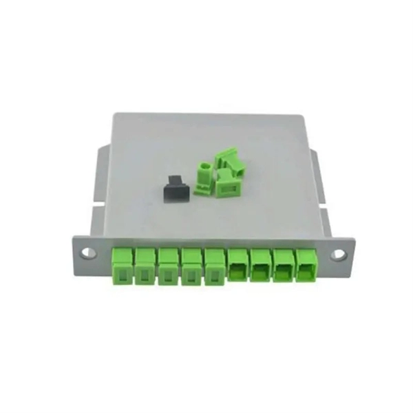
This diagram highlights media converters, switches, and cable types. Also thanks to Init7 (for the great service), r/FiberOptics and FS for providing me with what I needed to get this setup going. If you find this article useful and you are considering Init7 as your provider you can use my referral code “20700408098” to get CHF 111. - off hardware and also support me. Keeping this page as a placeholder for now. Have any questions? Talk with us directly using LiveChat. A fiber optics network diagram illustrates how high-speed data travels from an internet service provider to end users. By using light signals, fiber optics provide faster speeds and better reliability than. MS Visio has long been the default choice for drafting fiber network diagrams, and with the right stencil libraries it can be used to draw everything from backbone routes to detailed patch panel layouts. When fiber techs look for visio fiber stencils, they are usually solving a very practical. Be among the first to receive important product updates, insights and news. Fiber optic cable is used for everything from demarcation point wiring to network signal distribution to video signal extension. Often, fiber enters the structure to a centralized rack or data room where it is connected to a modem. The modem connects to a network switch which connects each remote.
[PDF]
Download a comprehensive set of Cable Tray Installation CAD Blocks in DWG format, ideal for electrical engineers, MEP designers, and industrial layout planners. This article shares simple ways to plan your cable trays and wiring. We want to help electrical engineers, technicians, and anyone working with electrical setups build safe and good systems. This collection includes installation details for ladder trays, perforated trays, solid-bottom trays, and wire mesh trays, along with. This guide provides step-by-step instructions on installing a cable tray on a wall, covering different types of cable trays, tools needed, and safety tips. The Ladder Tray features light, rugged, tubular steel construction. It is designed for. In industrial settings, electrical and instrumentation (E&I) cable trays or bridge racks play a critical role in organizing and supporting power, control, and signal cables across facilities. An effective layout ensures safety, minimizes interference, reduces maintenance time, and keeps the overall. ALL TO BE CLEANED WITH A COMMERCIALLY AVAILABLE CLEANSER PRIOR TO ALL MARKERS AFFIXED PRIOR TO INSTALLATION OF ANY CABLE. BONDING JUMPER SHALL BE INSTALLED FOR ELECTRICAL CONTINUITY ACROSS ALL DETAIL AT INTERFACES AND/OR CONDUIT BUSHINGS SHALL INSTALLED FCR ENTRY OF CABLES.
[PDF]

Welcome to our channel! In this video, we'll walk you through the process of wiring a home distribution box with a detailed connection diagram. more Welcome to our. Understanding the wiring diagram of an electrical panel box is essential for electricians and homeowners alike, as it allows them to troubleshoot any electrical issues, carry out repairs, or make additions to the system. What is Distribution Board? Distribution board. Hey, in this article we are going to see the Single Phase Distribution Box Wiring Diagram and Connection Procedure. A distribution board or distribution box is where the main power supply is distributed to multiple loads. And all the switching and protective devices are installed in the. That's why having a clear, detailed diagram of your home's distribution board wiring is essential. The diagram. Product Overview Renogy PMS1280 Smart Distribution Box is a centralized direct current (DC) power control hub specially designed for off-grid recreational vehicles, yachts, and motorhomes. The distribution box provides 12 circuit channels for load control as well as voltage and current detection.
[PDF]

They are characterized by numerous ports and high bandwidth, offering greater reliability, redundancy, throughput, and lower latency compared to access and aggregation switches. For a network with over 100 computers, a core switch is indispensable for ensuring stability and high. Data center-grade switches are characterized by high-quality business assurance and control recognition capabilities. They feature end-to-end flow control and backpressure mechanisms, ensuring stable and reliable data transmission, and smoothing out network surges. They offer higher reliability and. Aggregating Data Traffic: Accumulates data from the distribution and access layers and manages their routing and switching. High Performance: Guarantees dependable and quick data delivery, supporting substantial traffic with low latency. Redundancy and Fault Tolerance: This feature ensures network. A Core Switch is a critical device that operates in the backbone portion of a network, primarily used for high-speed data switching. It is part of the commonly used Network Switch hardware architecture and serves as a port device in the core layer.
[PDF]
Energy & Financial Markets: What Drives Crude Oil Prices? Greenhouse gas data, voluntary reporting, electric power plant emissions. Maps, tools, and resources related to energy disruptions and infrastructure. State energy information, including overviews, rankings, data, and. Energy is at the heart of today's geopolitical tensions, with traditional risks to fuel supply now accompanied by restrictions affecting supplies of critical minerals. International. The IEA examines the full spectrum of energy issues including oil, gas and coal supply and demand, renewable energy technologies, electricity markets, energy efficiency, access to energy, demand side management and much more. Through its work, the IEA advocates policies that will enhance the. The Energy Institute Statistical Review of World Energy™ analyses data on world energy markets from the prior year. Previously produced by bp, the Review has been providing timely, comprehensive and objective data to the energy community since 1952. By submitting your email you agree to receive. Reducing energy consumption and achieving energy savings is essential to deliver the European Green Deal. Energy from renewable sources reduces greenhouse gas emissions and lowers our dependence on imported fossil fuels.
[PDF]
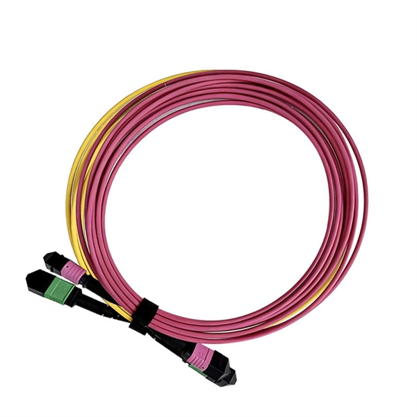
Region: Global | Format: PDF | Report ID: PMI1776 | SKU ID: 26441736 | Pages: 139 | Published : March, 2024 | Base Year: 2024 | Historical Data: 2020 - 2023. Region: Global | Format: PDF | Report ID: PMI1776 | SKU ID: 26441736 | Pages: 139 | Published : March, 2024 | Base Year: 2024 | Historical Data: 2020 - 2023. The global Waterproof Fiber Patch Cord Market size estimated at USD 875. 8 million in 2026 and is projected to reach USD 1165. 69 million by 2035, growing at a CAGR of 10% from 2026 to 2035. I need the full data tables, segment breakdown, and competitive landscape for detailed regional analysis and. The Global Waterproof Fiber Patch Cord Market size was valued at USD 805. This impressive rise indicates a CAGR of 10. 5% from 2023 to 2031, reflecting increasing demand in diverse applications. 0% during the forecast period 2024-2030. 2 USD Million in 2024. The Waterproof Fiber Patch Cord Market is expected to grow from 846. 9% during. Waterproof Fiber Patch Cord by Application (Network, Telecommunications, Military and Aerospace), by Types (Single-mode Fiber Optical Patch Cord, Multimode Fiber Optical Patch Cord), by North America (United States, Canada, Mexico), by South America (Brazil, Argentina, Rest of South America), by.
[PDF]
This research investigates the strain transfer characteristics of embedded FBG in pavement structure and materials by using the relevant theoretical models. Results indicate adhesive layer thickness and sheath modulus are the primary factors influencing the strain transfer coefficient. Fiber Bragg Grating Sensors (FBGS) are gaining increasing attention in the field of experimental stress analysis. They are very well suited to the new materials of glass and carbon fiber reinforced composites which are often used for highly stressed constructions, e. in airplanes and wind power. Fiber Bragg grating (FBG) exhibits strong resistance to electromagnetic interference and excellent linear strain response, making it highly promising for structural health monitoring (SHM) in pavement. The samples were made by the direct pressing method from fiberglass prepregs. Strain sensors based on FBGs are becoming an essential part of smart factory. Due to the difference in the physical and mechanical properties between the optical fiber, protective layer, adhesive layer, and the host material, the strains measured by a fiber Bragg grating (FBG) sensor may not be the actual strains of the host material, which impedes the reliable applications. Fiber Bragg Grating Sensors (FBGS) are gaining increasing attention in the field of experimental stress analysis. in airplanes and wind power.
[PDF]

Ever wondered how pigtail bolts—critical components in power line fittings—are made? Watch as we take you through the entire manufacturing process step by st. How to Make Electrical Pigtails: This is a basic tutorial on what electrical pigtails are and how to make them. Disclaimer: Always use multiple sources and do your homework before performing any electrical work. Also, make sure all work is done within national and local code. Let's look at how to make pigtail wire links below. Also, it can join several wires to become a single conductor for electrical connections. Let us suppose I had 14 shielded wires to bring into a 15-pin connector where only one pin was available for shield grounds. Imagine how fat a lump there will be if all the shield terminations are located right next to. Bulb to Socket & Component to Connector Cross Reference Guide des spirales de raccord et des douilles Renvois ampoules/douilles et composants/connecteurs Guía de cables flexibles y adaptadores Referencias a bombillas/adaptadores y componentes/conectores NAPA®ECHLIN IGNITION, EMISSION, ENGINE. Pigtail connections are most frequently used to ground a switch or electrical outlet and for electrical devices that need to connect to multiple circuit wires. They also come in handy to lengthen circuit wires that are too short to reach a device. A pigtail is composed of three strands of wire.
[PDF]
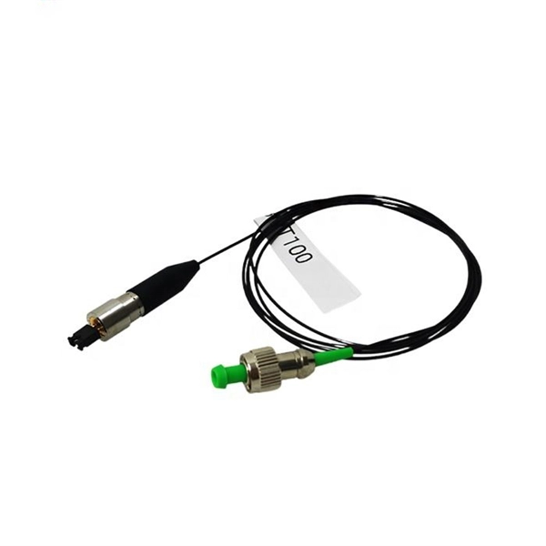
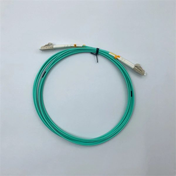
A fiber optic pigtail is a short length of optical fiber —typically 0. 5m to 2m—that has a factory-terminated connector on one end and bare fiber on the other end. The connector end is polished and tested under factory conditions, ensuring low insertion loss and high return loss. They are the bridge between fiber optic cables in the field and the equipment or patch panels that manage them. By combining factory-installed connectors with spliced bare fiber, pigtails ensure that network installers can create fast, reliable, and cost-effective terminations. Without pigtails. What is a Fiber Optic Pigtail, and What Is It Used For? Written by Ben Hamlitsch, trueCABLE Technical and Product Innovation Manager RCDD, FOI A fiber optic pigtail is a type of fiber optic cable with only one end that has a factory-terminated connector and the other end exposed as bare fiber. ) fitted on one end and the other end undressed (for connection through fusion or splicing) to the main fiber optic cable. It is usually suitable for field termination using a mechanical or fusion splicer. Compared with quick termination or epoxy and polish connections placed on the field. Fiber optic pigtail offers an optimal way to joint optical fiber, which is used in 99% of single-mode applications. This post contains some basic knowledge of fiber optic pigtail, including pigtail connector types, fiber pigtail classifications.
[PDF]
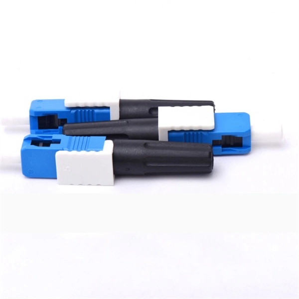
These connectors have a universal termination kit that includes all the components needed for installation. The instructions provided describe the assembly procedure for installing the connectors, including identifying the components, preparing the fiber, and assembling. FASTConnect® field-installable connectors are factory pre-polished connectors that completely eliminate the need for hand polishing in the field. Proven mechanical splice technology ensuring precision fiber alignment, a factory pre-cleaved fiber stub and a proprietary index-matching gel combine to. Comes in a pack of 6 connectors. Comparable to OCC part number FXC-ST8-6 and Corning part number 95-200-51. FAST Connectors are compatible with 250 µm and 900 µm optical fibers, as well as 4. 8 mm (SC only) cordage. A factory-installed wedge clip (included. FAST Connectors are designed for use with single-mode or multimode fiber optic cable and come in SC, ST, and LC configurations. ead these instructions carefully before proceeding. Different termination options after cleaving the fiber are provided for each fiber type ys wear eye protection.
[PDF]