This report studies the global Distribution Boxes production, demand, key manufacturers, and key regions. IMARC Group's comprehensive DPR report, titled "Corrugated Box Manufacturing Plant Project Report 2026: Industry Trends, Plant Setup, Machinery, Raw Materials, Investment Opportunities, Cost and Revenue," provides a complete roadmap for setting up a corrugated box manufacturing unit. The corrugated. How will the increasingly important e-commerce market shape box demand and design going forward? Demand for corrugated and paperboard boxes in the US totaled $47 billion in 2024 and is forecast to surpass $52 billion in 2029, with volume reaching 31 million tons. This report is a detailed and comprehensive analysis of the world market for Distribution Boxes, and provides market size (US$ million) and Year-over-Year (YoY) Growth, considering 2022 as the. The global Distribution Boxes market was valued at US$ million in 2023 and is anticipated to reach US$ million by 2030, witnessing a CAGR of % during the forecast period 2024-2030. 5 Billion in 2023 to USD 48. Additionally, it. The integration of Internet of Things (IoT) technology in distribution boxes allows for remote monitoring and control, providing better operational efficiency and reducing downtime. These advancements are attracting significant investments from both public and private sectors, further driving the.
[PDF]
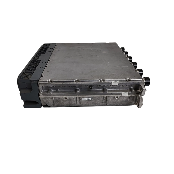
Using a multimeter, check continuity between the black connector and the marked pin of the optocoupler input that is not working. If there is no continuity, the possible causes are: Connect a 5 V to 24 V signal to the input being tested. Measure the voltage at the marked. Using a multimeter, you can perform several tests to assess the functionality of an optocoupler. Each test targets a specific aspect of the optocoupler's operation. An optocoupler is an essential electronic component that transfers signals without a direct electrical connection. more n this video, you will learn how to test an optocoupler (optoisolator) using a. Optocoupler is one type of ICs, It isolates input and output section by using optical technology this feature increase safety of circuit. Optocoupler has many part number, different part number has different output type so before checking it has to use part number to research with datasheet and. If any optically isolated input on the controller is not working, follow the steps below to identify the cause. For our demo purposes, we will be using the PC817, a commonly used transistor output optocoupler in electronics. An opto-isolator contains a source (emitter) of light, almost always a near infrared light-emitting diode (LED), that converts electrical input signal into light, a closed optical channel (also called dielectrical channel, and a photo sensor, which detects incoming light and either generates.
[PDF]
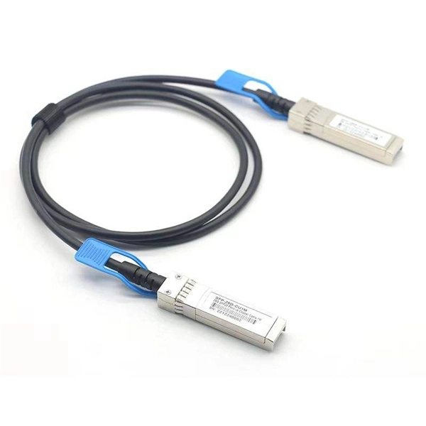
A common test setup to evaluate Stressed Receiver Sensitivity involves measuring the Optical Modulation Amplitude (OMA) using a square wave, per the standard guidelines. Receiver sensitivity stands as a critical parameter impacting an optical transceiver's functionality. It denotes a module's capability to function in challenging environments and aids network operators in determining the system's maximum reach or link margin. These metrics provide insights into how well your transceivers perform under different conditions, ensuring seamless data transmission. Optical. Whether you're a network engineer validating new inventory or an integrator preparing for deployment, knowing how to test optical transceiver modules can save time, reduce failures, and ensure SLA compliance. Unchecked optical modules can cause: Testing ensures compliance with IEEE 802. 3 and MSA. In optical communication systems, sensitivity is a measure of how weak an input signal can get before the bit-error ratio (BER) exceeds some specified number. The standards body governing the application sets this specified BER. For example, SONET specifies that the BER must be 10 -10 or better. Why Fiber Optic Transceiver Testing is Important? Identify faults and failures: Transceiver testing helps in identifying any faults.
[PDF]
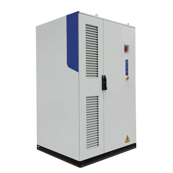
In this article, you will learn the step-by-step process of testing your solar panels using a multimeter. We will cover the essential tools you need, the specific measurements to take, and how to interpret the results. By the end of this guide, you will be equipped with the knowledge to diagnose. Solar panels are usually tested under standard conditions using a light source that mimics the light from the sun on a clear day. You can use the following method if you want to test your solar panel under standard conditions. Testing solar panels is easy with a multimeter! To test the current. Your multimeter is your best friend when testing solar panels. You can use it to check: Here's how: Multimeter — I recommend getting one that is auto-ranging. Also, a simple voltmeter won't work here. You need a multimeter that can measure both volts and amps. Locate the open circuit voltage. Learning to test a solar panel with a multimeter is an investment in your knowledge and ability to manage your own solar energy system or provide valuable services in the growing solar industry. Measure Voc (open circuit voltage) — if it reads 0V, the panel or wiring is dead. If it reads 60–80 % of rated, a bypass diode has failed. Perfect for DIY solar builders, RV owners, o. more Audio tracks for some languages.
[PDF]
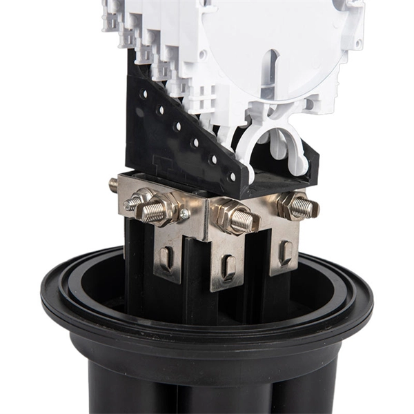
An OTDR is a powerful tool that helps technicians and engineers assess the health of fiber optic cables. OTDRs inject high-powered light pulses into the fiber using specialized laser diodes. As these light pul.
[PDF]