Passive media components such as cables, cable splices, and connectors cause attenuation. Although attenuation is significantly lower for optical fiber than for other media, it still occurs in both multimode and single-mode transmissions. Two fundamental mechanisms cause attenuation inside the fiber itself: absorption and scattering. These are intrinsic to the glass, meaning they exist even in a perfectly manufactured, perfectly installed fiber. Scattering is the bigger factor at the wavelengths most networks use. The silica glass. Optical attenuation is the gradual loss of flux (light intensity) as an optical signal travels through a fiber. Measured in decibels (dB), it's the logarithmic ratio of the output power to the input power. Every network has a "loss budget". F iber optic networks rely on the efficient transmission of light signals to deliver high-speed data over long distances. However, various factors can cause signal degradation, leading to performance issues and reduced network reliability. You may see slower speeds and less steady connections when signal loss goes up. Things like impurities in the fiber core and reflections at the core-cladding edge cause this drop. This can be due to a variety of factors: scattering and absorption, intrinsic. Signal attenuation in fiber optics is a key concept in telecommunications. It affects how far a signal can travel without losing.
[PDF]
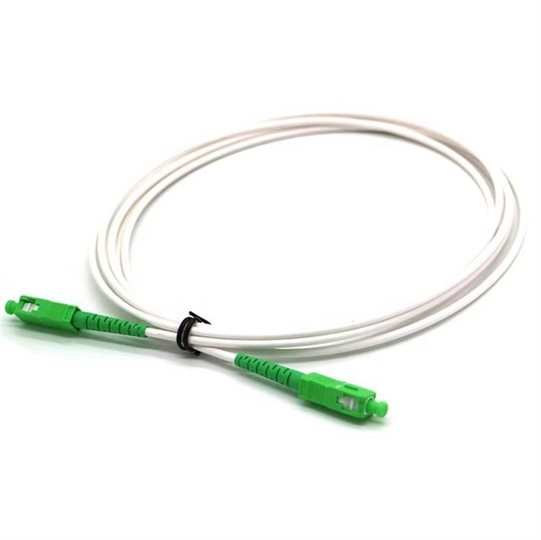
The answer has to do with the connector endface polish, or the angle of connection, and the good news is connectors also follow industry-standard color codes. Fiber connectors are often used as the terminations of optical fiber cables to provide non-permanent connections between fiber-coupled devices (a kind of removable fiber joints). They are used in a similar manner as electrical connectors. This allows for quickly connecting and disconnecting of fiber optic cables without splicing. The connector features a ferrule, the connector end piece that holds and secures the fiber and aligns it for light. The fiber connector is called a fiber optic or optical fiber connector. A link's transmit signal (Tx) must match its corresponding receiver (Rx) at the other end. Although it may seem obvious, fiber optic polarity is a frequent source of confusion and. Fiber optic patch cables consist of the connectors on the ends of the fiber cable. The options on these cables dictate the fiber type, connector type, polarity, and polish type. The fiber types are SMF (Single-mode fiber) and MMF (multimode fiber). The most common connector types are LC, SC. The fiber connector types, sometimes referred to as terminations, link fiber optic cables together through terminals, switches, adapters, and patch panels, by bridging the gap between their internal glass fibers that transmit the data down the length of the cable. The ferrule, a cylindrical.
[PDF]
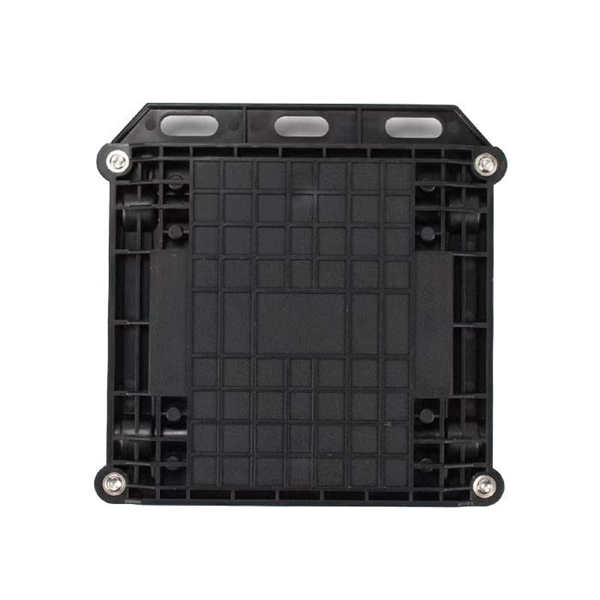
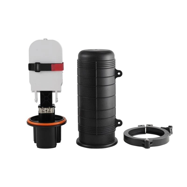
Main Purpose: 6-core fiber optic distribution box, widely used in FTTH project, easy to construct and provide good protective operation. Fiber optic terminal junction boxs are designed to provide a safe and organized solution for managing fiber optic cables in indoor and outdoor. FBR-11606 Fiber-Optic Distribution Box, 6-Core is a high quality product by Bud Industries used for electronic enclosure applications. The HTB8009 6 Ports FTTH Termination Box is a compact, multi-functional distribution enclosure specially designed for final fiber termination at the user end in fiber-to-the-home (FTTH) applications. Built from UV-resistant ABS material, the box combines durability with a sleek form factor, making. The structure of the product is compact, which can meet the needs of various optical cable installation, convenient construction and reliable sealing. Water-proof design with IP65 portection level. Integrated with splice cassette and cable management system. The type of installation for 6 core distribution box is wall-mounted. The entry size of the. Max. Capacity Gcabling is a leading fiber box manufacturer & supplier. We can manufacture and supply a wide range of fiber termination boxes with 20+ years of experience.
[PDF]
Prices typically range from about $0. 50 per foot for fiber optic cable and basic installation, depending on indoor vs outdoor routing, distance, and terrain. Commercial building installations with 100-200 network drops generally range from $15,000 to $30,000. Single-mode fiber costs less per foot than multimode fiber, but it requires more. Buyers typically see a wide range in fiber cost per foot depending on cable type, installation method, and terrain. The main cost drivers include cable type (single-mode vs multimode), whether the run is indoors or outdoors, trenching or direct burial requirements, and labor time. This guide presents cost ranges in USD and highlights how per-foot pricing translates to total project costs for typical. The Fiber Broadband Association has partnered with Cartesian to research the cost of deploying fiber and provide insight on how these costs are evolving over time. In preparing this second edition of the Fiber Deployment Cost report, Cartesian gathered inputs from a wide variety of firms building. 1) Proofing and Placement - Per foot pricing for proofing and placement of approximately 1,856,332 ft (351. 864F Prysmian non-armored ribbon cable (24 Fibers per ribbon) into existing empty. conduit (price includes the provision of redline documentation, fiber cable. Buyers typically pay for the cable itself, termination hardware, and professional installation. The following guide outlines typical costs, with practical ranges in USD.
[PDF]
This step-by-step guide aims to provide a comprehensive understanding of the techniques and considerations involved in successfully connecting optical fibers, offering invaluable insights for professionals and enthusiasts in the field. In high-speed data networks, the seamless integration of fiber optic cables with SFP (Small Form-Factor Pluggable) modules is critical for reliable signal transmission. SFP transceivers bridge electrical and optical signals, making them indispensable in data centers, telecom networks, and. Proper connection of fiber optic cables is essential to harness these benefits fully, as even minor errors can lead to significant performance issues like signal loss. This article will guide you through the necessary tools, materials, and methods on how to connect fiber optic cables effectively. This section describes how to install optical transceivers on the SFP or SFP+ ports and connect them to the ports of the peer device using optical fibers according to the network plan. The USG supports both 1 Gbit/s, 10 Gbit/s, and 40 Gbit/s optical modules. The optical modules at both ends are. There are many types of fiber optic connectors, including SC, LC, FC, ST, D4, MU, MT/MPO, etc. These connectors can be divided into single-mode and multi-mode fiber optic connectors according to their structure and purpose. In this tutorial.
[PDF]

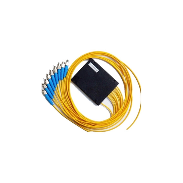
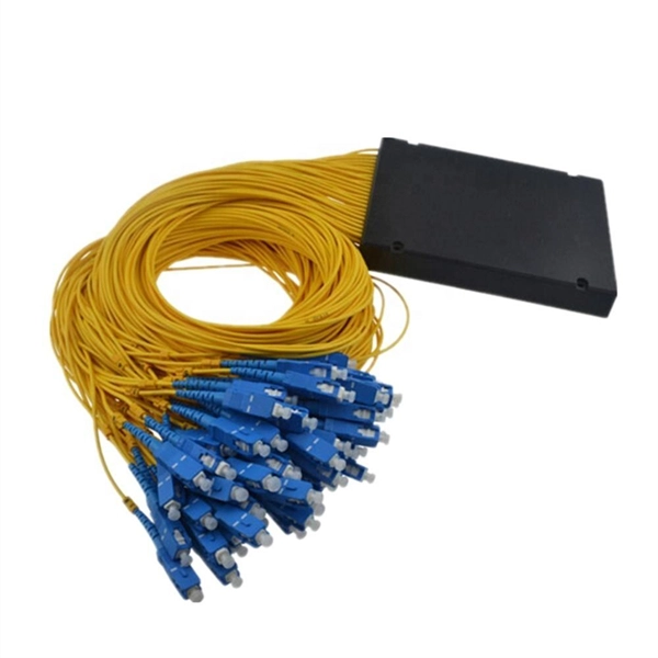
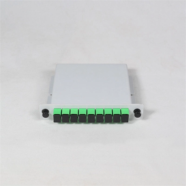
Optical splitters enable a signal on an optical fiber to be distributed among two or more fibers. Since fiber splitters contain no electronics nor require power, they are an integral component and widely used in most fiber-optic networks. A fiber optic splitter is a passive optical component that divides a single incoming optical signal into two or more outgoing signals, or combines multiple incoming signals into one. Unlike active devices (which require power), splitters operate without electricity, relying solely on the physics of. Optical cables, also known as fiber optic cables, consist of thin strands of glass or plastic fibers surrounded by a protective casing. These fibers transmit data as light signals, which are converted into electrical signals at the receiving end. The benefits of optical cables are numerous. A fiber-optic splitter, also known as a beam splitter, is based on a quartz substrate of an integrated waveguide optical power distribution device, similar to a coaxial cable transmission system. Its primary role is in Passive Optical Networks (PON), which are the foundation of. A fiber broadband provider typically determines and overall split ratio for the network, such as 1x32 or 1x64, and uses combinations of splitters to meet that ratio with each PON port. 1x32 splits were common in North America for G-PON architectures. As XGS-PON continues to be adopted, some service.
[PDF]
In this video, I walk you through my personal method of prepping and installing a 1:16 fiber optic splitter inside a sealed, weatherproof distribution box getting it ready for field deployment at a site. This is the way I've found to be clean, efficient, and reliable based on my experience in the. Optical splitters offer a cost-effective and dependable solution across various fiber optic applications. Also known as optical splitters, fiber splitters, or beam splitters, these devices are integrated waveguides ensuring wide bandwidth and minimal loss in high-frequency applications. They. How to install the splitter distribution box is the important information we need to know. This article includes the following: 1. Install the fixture 2. Ground the installation system 1. Have any questions? Talk with us directly using LiveChat. Fiber optic cable s transmit data using light signals, allowing for faster and more efficient data transfer compared to traditional copper cables. In the world of fiber optics, a crucial component for distributing signals is the fiber optic splitter box.
[PDF]
The short answer is no - RJ45 connectors are designed for electrical Ethernet signals, while fiber optics transmit light pulses through glass or plastic. However, modern networks often combine both technologies. With the launch of the new Wi-Fi 7 routers BE800 and BE900, our home routers have begun to utilize the high speeds that come with added SFP+ Compatibility. The SFP+ port is a high-speed optical-to-optical signal conversion port, mainly used for 10G Ethernet and Fiber Channel network applications. A. Small Form-factor Pluggable (SFP) is a compact, hot-pluggable network interface module format used for both telecommunication and data communications applications. Think of it as the “translator” for your network equipment, converting electrical signals into optical signals. SFP (Small Form-factor Pluggable) modules, also known as mini-GBICs (Gigabit Interface Converters), are commonly used in network switches and routers to provide flexible and modular network connectivity options. These types of ports can be used with various transceivers thereby allowing the system administrators to customize connectivity according to their network topology. SFP modules and DAC cables are used inside SFP28/SFP/SFP+ slots on UniFi or client devices. These slots allow for versatile connectivity options using different types of cabling. SFP+ and SPF28 DAC Cables: Establishing 1/10/25 Gbps connections over short distances, e. between devices in the same.
[PDF]
This video provides a step-by-step guide on how to efficiently install optical splitter into a fiber terminal box, demonstrating a professional and reliable deployment for optical distribution network solution ( https://www. com/c/optical-distribu. We'll also share tips to minimize signal loss and ensure optimal performance. What Is a Splitter and Why Cascade Them? A splitter divides a single input signal into. When employing the first-level splitting method in a residential network, optical splitters offer flexibility for indoor or outdoor installation. Indoor options encompass locations like the community's central computer room, building's weak current well, or floor wiring box. Optical cables can be. If you have fiber optic cable inside your home, it is possible to install a cable into the home input then split the signal so you can connect the signal to two different television hookups. Insert one end of the fiber optic cable into the "In" port accessible through your wall. The splitter box contains a splitter, which is a passive optical device that divides the incoming light signal. How to install and use fiber optic cable splitter? In fact, the installation of the fiber optic cable splitter is very simple, because it is already a cable terminal product, mainly to see whether it is with a fiber connectors or not, and the packaging type. For example, plc splitter without.
[PDF]
With a variety of kit options available, you can choose between the easy-to-use Quick Clean™ Cleaners, the convenient cleaning cube/card, and the best optic solvent pen to clean both patch cords and fiber.
[PDF]
The evolution of fiber optic transmission systems has seen advancements such as dense wavelength division multiplexing (DWDM), coherent transmission technology, modulation format improvements, increased transmission speeds (e., 100 Gbps, 400 Gbps), and the adoption of. The winding journey of fiber optics is a story of persistent progress. From Daniel Colladon's 1841 demonstration of light guidance in water to recent advances empowering multi-terabit infrastructure, researchers continuously pushed the boundaries of optical communication. Early steps like total. Created by the Fiber Optic Association as an educational project to help document the history of the development of fiber optics for communications. Dates, of course, are often approximate, as putting a firm date on the introduction of a new technology is often impossible! the most important. Discover the latest developments in fiber-optic communications with the newest edition of this leading textbook In the newly revised fifth edition of Fiber-Optic Communication Systems, accomplished researcher and author, Dr. Agrawal, delivers brand-new updates and developments in the. The evolution of fiber optic networks has been a steady and methodical journey of technological advancements that have revolutionized the way we communicate and transfer data. From its inception as a theoretical concept in the 1960s, fiber optics has undergone significant developments, resulting in.
[PDF]
Interactive anomalies of pipelines represent important contributors to pipeline incidents, but monitoring interactive anomalies is challenging. This paper presents an approach to monitor interactive bend.
[PDF]
In this video, we'll guide you through the process of configuring a Huawei Switch for your network. Whether you're setting up a new switch or optimizing your existing network infrastructure, this step-by-step tutorial will help you get the job done efficiently. This document provides campus networks typical configuration examples and feature typical configuration examples. "Campus Networks Typical Configuration Examples" provides typical campus network networking modes and a variety of deployment examples. This document is for switches running V200R003C00 and later. In this video, we'll guide you. Saving Configuration: Save changes to make the configuration permanent: Checking Settings: Use commands like display user-interface console 0 to verify correct configuration. Exiting the Device: Log out of the device after completing the configuration. Enabling Telnet Service and Granting Access on. The Combo interface, also known as the optical-electrical multiplexing interface, consists of two Ethernet ports (one optical and one electrical) on the device panel, and there is only one forwarding interface inside the device.
[PDF]
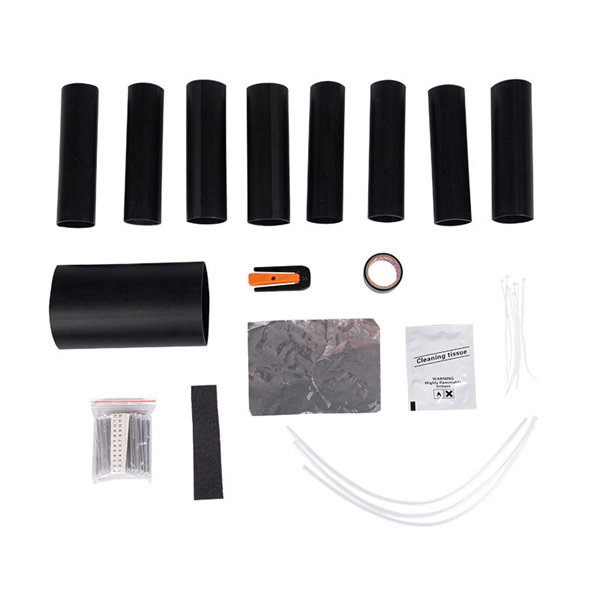
We terminate fiber optic cable two ways - with connectors that can mate two fibers to create a temporary joint and/or connect the fiber to a piece of network gear or with splices which create a permanent joint between the two fibers. Proper connection of fiber optic cables is essential to harness these benefits fully, as even minor errors can lead to significant performance issues like signal loss. These terminations must be of the right style, installed in a. Running fiber internally involves extending this high-speed link from the service entry point to a centralized location, such as a dedicated media closet or network rack. This DIY effort is undertaken to maximize performance, improve aesthetics, or relocate the Optical Network Terminal (ONT) to a. In this video, we'll guide you through preparing and terminating fiber optic cables using SimplyFiber products, known for their high quality, ease of use, and reliability. more Audio tracks for some languages were automatically generated. Two types of splices are used in fiber optic cabling one is Mechanical the other is Fusion. Whether you're installing a new network, expanding an existing one, or. But here's the thing: how you connect fiber optic cable really matters. A shaky connection means weaker signals, dropped streaming, or slow uploads. Get the hookup right, and you'll enjoy streaming, gaming, and video calls without interruptions.
[PDF]
The core principle of fiber optic splicing is to achieve low-loss, high-strength junctions between fiber ends. This involves three key steps: preparation, alignment, and bonding. Let's break it down technically:. At the core of this system's precision and reliability are Fiber Optic Splice Boxes—the unsung heroes that house and protect the delicate junctions where fiber cables are joined. The integrity of these enclosures is paramount to network performance. This guide optimizes the original text by delving. A splice box (also known as splice distributor) is a housing in which fiber optic cables begin or end. Key Functions Typical Applications ZION FTB Highlights In essence: The Fiber Terminal Box is an end-user termination device for small-scale distribution. ■ What Is a Fiber. Fiber optic cables are the lifeline of modern telecommunications, delivering high-speed data with minimal loss. However, installing and maintaining these networks requires seamless connections between fiber segments—a process known as fiber optic splicing. Understanding how it works is essential for anyone interested in telecommunications or network infrastructure. Essential for mending faults or scaling networks, splicing underpins the backbone of contemporary communications. In this comprehensive guide.
[PDF]