Passive media components such as cables, cable splices, and connectors cause attenuation. Although attenuation is significantly lower for optical fiber than for other media, it still occurs in both multimode and single-mode transmissions. Two fundamental mechanisms cause attenuation inside the fiber itself: absorption and scattering. These are intrinsic to the glass, meaning they exist even in a perfectly manufactured, perfectly installed fiber. Scattering is the bigger factor at the wavelengths most networks use. The silica glass. Optical attenuation is the gradual loss of flux (light intensity) as an optical signal travels through a fiber. Measured in decibels (dB), it's the logarithmic ratio of the output power to the input power. Every network has a "loss budget". F iber optic networks rely on the efficient transmission of light signals to deliver high-speed data over long distances. However, various factors can cause signal degradation, leading to performance issues and reduced network reliability. You may see slower speeds and less steady connections when signal loss goes up. Things like impurities in the fiber core and reflections at the core-cladding edge cause this drop. This can be due to a variety of factors: scattering and absorption, intrinsic. Signal attenuation in fiber optics is a key concept in telecommunications. It affects how far a signal can travel without losing.
[PDF]
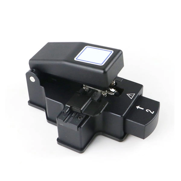
Even when splicing identical fibers together, if they are not perfectly aligned, optical power will be lost and attenuation across the splice will exist. The performance of a fiber optic splice is determined by a number of factors, including the quality of the fiber, the cleanliness of the splice, and the techniques used to make the splice. Intrinsic factors, such as the refractive index of the fiber, are those that are inherent to the fiber itself. Fiber optic cable splicing is the process of joining two fibers end-to-end to create a continuous optical path. In PON and FTTx networks (e., FTTH, FTTP, FTTM), splicing is essential for extending cables, repairing breaks, or connecting backbone and distribution lines. To protect these vulnerable. Fiber loss, also called fiber optic attenuation or attenuation loss, refers to the loss of signal between input and output. Losses can be introduced by various means such as intrinsic material absorption, scattering, bending, connector loss and more. The absorption is caused by the absorption of the light and conversion to heat by molecules in the glass. Primary absorbers are residual OH+ and dopants used to modify the refractive index of the glass. Unlike using connectors, which are designed for frequent connection and disconnection at patch panels, splicing creates a permanent, stable joint with minimal light loss. This process is fundamental to building and.
[PDF]
Our list for Fiber optic products suppliers in Venezuela is one of the most comprehensive in the industry. As of May, 2026, we have compiled data on 20 verified listings. Zulia makes up approximately 40% of all Fiber optic products suppliers in. Optromix R&D team, established in 2004, has an extensive experience in the development of fiber optic products and solutions, based on the advanced research work and patents of internationally recognized scientists. Manufacturer Based in Newton, MA. When producing fiber. We offer a full range of FRP products including gratings, railings, ladders, stairs, plates and work platforms. In addition to our standard FRP stair solutions and structural products, we provide fiberglass reinforced plastic products with resin formulations engineered for specific corrosion. There are 23 Fiber Optic Products Suppliers in Venezuela as of October 8, 2024; which is an 0. 00% increase from 2023. Of these locations, 21 Fiber Optic Products Suppliers which is 91.
[PDF]
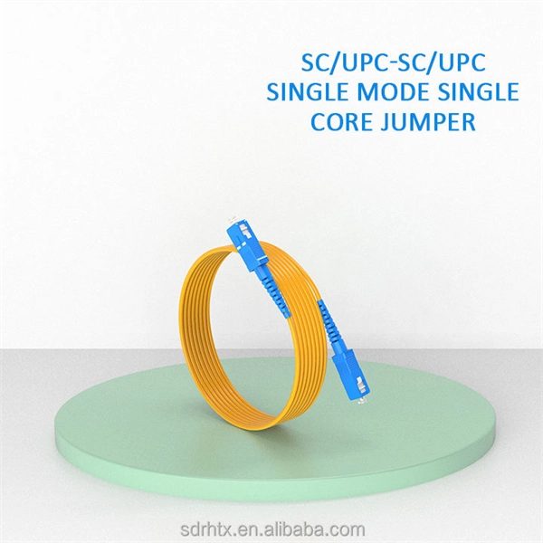
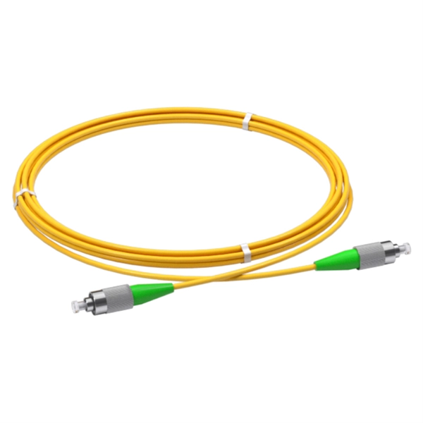
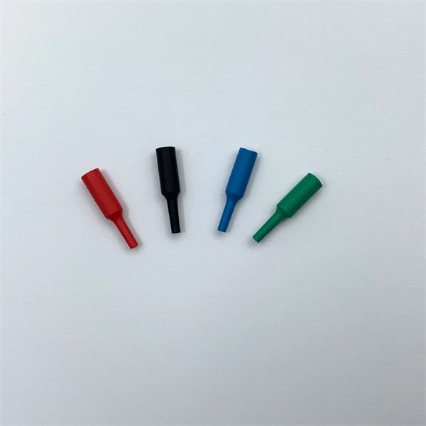
The answer has to do with the connector endface polish, or the angle of connection, and the good news is connectors also follow industry-standard color codes. Fiber connectors are often used as the terminations of optical fiber cables to provide non-permanent connections between fiber-coupled devices (a kind of removable fiber joints). They are used in a similar manner as electrical connectors. This allows for quickly connecting and disconnecting of fiber optic cables without splicing. The connector features a ferrule, the connector end piece that holds and secures the fiber and aligns it for light. The fiber connector is called a fiber optic or optical fiber connector. A link's transmit signal (Tx) must match its corresponding receiver (Rx) at the other end. Although it may seem obvious, fiber optic polarity is a frequent source of confusion and. Fiber optic patch cables consist of the connectors on the ends of the fiber cable. The options on these cables dictate the fiber type, connector type, polarity, and polish type. The fiber types are SMF (Single-mode fiber) and MMF (multimode fiber). The most common connector types are LC, SC. The fiber connector types, sometimes referred to as terminations, link fiber optic cables together through terminals, switches, adapters, and patch panels, by bridging the gap between their internal glass fibers that transmit the data down the length of the cable. The ferrule, a cylindrical.
[PDF]
Modern fiber-optic communication systems generally include optical transmitters that convert electrical signals into optical signals, optical fiber cables to carry the signal, optical amplifiers, and optical receivers to convert the signal back into an electrical signal. The information transmitted is typically digital information generated by computers or telephone systems. Transmitters The most commo. OverviewFiber-optic communication is a form of for from one place to another by sending pulses of or through an. The light is a form of. First developed in the 1970s, fiber-optics have revolutionized the industry and have played a major role in the advent of the. Because of its advantages over electrical transmission, optical fiber. is used by telecommunications companies to transmit telephone signals, Internet communication and cable television signals. It is also used in other industries, including medical, defense, governmen.
[PDF]
This step-by-step guide aims to provide a comprehensive understanding of the techniques and considerations involved in successfully connecting optical fibers, offering invaluable insights for professionals and enthusiasts in the field. In high-speed data networks, the seamless integration of fiber optic cables with SFP (Small Form-Factor Pluggable) modules is critical for reliable signal transmission. SFP transceivers bridge electrical and optical signals, making them indispensable in data centers, telecom networks, and. Proper connection of fiber optic cables is essential to harness these benefits fully, as even minor errors can lead to significant performance issues like signal loss. This article will guide you through the necessary tools, materials, and methods on how to connect fiber optic cables effectively. This section describes how to install optical transceivers on the SFP or SFP+ ports and connect them to the ports of the peer device using optical fibers according to the network plan. The USG supports both 1 Gbit/s, 10 Gbit/s, and 40 Gbit/s optical modules. The optical modules at both ends are. There are many types of fiber optic connectors, including SC, LC, FC, ST, D4, MU, MT/MPO, etc. These connectors can be divided into single-mode and multi-mode fiber optic connectors according to their structure and purpose. In this tutorial.
[PDF]
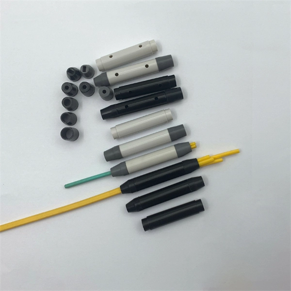
Get the wrong connector type, the wrong polish, or skip proper fusion splicing technique—and you're looking at elevated signal loss, increased back reflection, and a field termination that fails certification. Once you nail the logic chain— raw fiber → protected cable → spliced pigtail interfaces → flexible patching —you control loss budgets, installation time, and maintenance risk. Key takeaway: Treat the four items like a relay team. Each runs a specific leg so your network hits performance targets. In the intricate ecosystem of fiber optic networks, two components play a critical role in ensuring seamless connectivity: patch cords and pigtails. While both are essential for linking fibers to devices or other cables, they serve distinct purposes and are designed for specific scenarios. Executive Summary: A fiber optic pigtail is one of the most commonly specified yet least understood components in structured cabling. Despite their widespread use and numerous advantages, there are some circumstances in which they might not be the ideal option. A fiber optic pigtail is very practical for on-site terminations where fusion or mechanical splicers are used. Preterminated connectors offer several advantages over. Today, I'll show you how to pick the right patch cord or pigtail — step by step. A Fiber Patch cord connects two devices. You plug it into a switch, router, or patch panel. It's ready to use out of the box. A pigtail is for splicing.
[PDF]

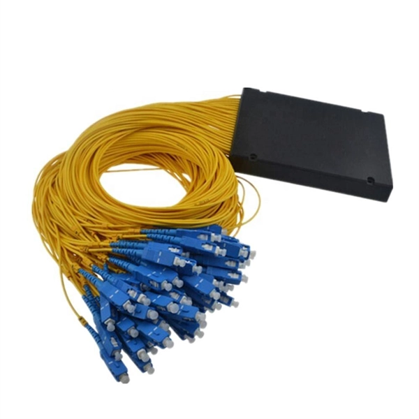
Optical splitters enable a signal on an optical fiber to be distributed among two or more fibers. Since fiber splitters contain no electronics nor require power, they are an integral component and widely used in most fiber-optic networks. A fiber optic splitter is a passive optical component that divides a single incoming optical signal into two or more outgoing signals, or combines multiple incoming signals into one. Unlike active devices (which require power), splitters operate without electricity, relying solely on the physics of. Optical cables, also known as fiber optic cables, consist of thin strands of glass or plastic fibers surrounded by a protective casing. These fibers transmit data as light signals, which are converted into electrical signals at the receiving end. The benefits of optical cables are numerous. A fiber-optic splitter, also known as a beam splitter, is based on a quartz substrate of an integrated waveguide optical power distribution device, similar to a coaxial cable transmission system. Its primary role is in Passive Optical Networks (PON), which are the foundation of. A fiber broadband provider typically determines and overall split ratio for the network, such as 1x32 or 1x64, and uses combinations of splitters to meet that ratio with each PON port. 1x32 splits were common in North America for G-PON architectures. As XGS-PON continues to be adopted, some service.
[PDF]
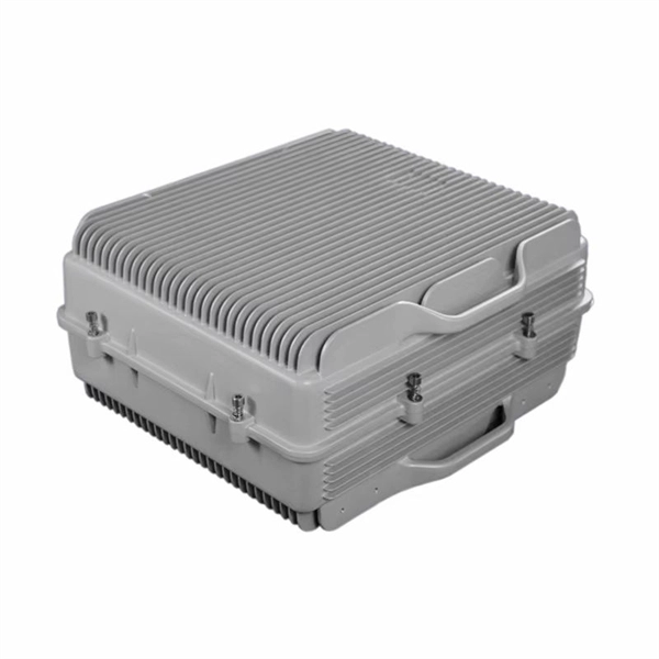
In this video, I walk you through my personal method of prepping and installing a 1:16 fiber optic splitter inside a sealed, weatherproof distribution box getting it ready for field deployment at a site. This is the way I've found to be clean, efficient, and reliable based on my experience in the. Optical splitters offer a cost-effective and dependable solution across various fiber optic applications. Also known as optical splitters, fiber splitters, or beam splitters, these devices are integrated waveguides ensuring wide bandwidth and minimal loss in high-frequency applications. They. How to install the splitter distribution box is the important information we need to know. This article includes the following: 1. Install the fixture 2. Ground the installation system 1. Have any questions? Talk with us directly using LiveChat. Fiber optic cable s transmit data using light signals, allowing for faster and more efficient data transfer compared to traditional copper cables. In the world of fiber optics, a crucial component for distributing signals is the fiber optic splitter box.
[PDF]
The projected fiber optic splicer job growth rate is 6% from 2018-2028. About 13,600 new jobs for fiber optic splicers are projected over the next decade. — (September 22, 2025)—Today the Fiber Broadband Association (FBA) and NCTI, a leading broadband and network training solutions provider, unveiled the results of a joint workforce preparedness survey. The findings have been published in a paper titled, “Employer Workforce. The fiber optic splicer market is experiencing robust growth, driven by the expanding global telecommunications infrastructure and the increasing demand for high-speed internet connectivity. The market's Compound Annual Growth Rate (CAGR) is estimated at 7% for the period 2025-2033, indicating a. Government broadband funding is flowing, but the technicians and engineers to build fiber networks don't exist in sufficient numbers. Telecoms are getting creative with recruiting. The Bipartisan Infrastructure Law allocated $42. 5 billion for broadband deployment through the BEAD program. State. Data-driven look at fiber optic and broadband technician careers, including the 178,000-worker shortage driven by $42. 5B in federal broadband investment, salary data, certification paths, and why this may be the best-timed trade career in a generation. Fiber network deployments in the US, while hitting a bit of a slowdown, are proceeding apace and will ramp up significantly as grants start.
[PDF]
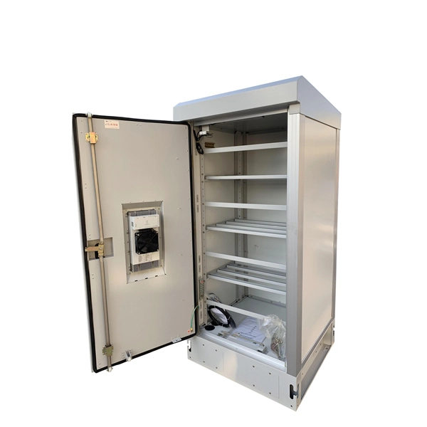
This video provides a step-by-step guide on how to efficiently install optical splitter into a fiber terminal box, demonstrating a professional and reliable deployment for optical distribution network solution ( https://www. com/c/optical-distribu. We'll also share tips to minimize signal loss and ensure optimal performance. What Is a Splitter and Why Cascade Them? A splitter divides a single input signal into. When employing the first-level splitting method in a residential network, optical splitters offer flexibility for indoor or outdoor installation. Indoor options encompass locations like the community's central computer room, building's weak current well, or floor wiring box. Optical cables can be. If you have fiber optic cable inside your home, it is possible to install a cable into the home input then split the signal so you can connect the signal to two different television hookups. Insert one end of the fiber optic cable into the "In" port accessible through your wall. The splitter box contains a splitter, which is a passive optical device that divides the incoming light signal. How to install and use fiber optic cable splitter? In fact, the installation of the fiber optic cable splitter is very simple, because it is already a cable terminal product, mainly to see whether it is with a fiber connectors or not, and the packaging type. For example, plc splitter without.
[PDF]
This complete guide explores everything you need to know about ODFs — from their structure, types, and key components, to installation best practices and modern design trends. Whether you're building a central office, data center, or FTTx distribution network, understanding the right ODF. In modern data centers and enterprise networks, Optical Distribution Frames (ODF) serve as the backbone for organizing, terminating, and managing fiber optic connections. This article explores the types, components, applications, installation, and maintenance best practices, providing a. An Optical Distribution Frame (ODF) is the central hub for fiber splicing, termination, patching, and cable protection in modern optical networks. As data centers, enterprises, telecom operators, and smart-building infrastructures deploy increasingly dense fiber links, ODFs provide the structured. Achieve successful cable management, handle high amounts of fiber cable and add density to fiber frames with the new DCX Optical Distribution Frame (ODF) System which features innovations like flippable cassettes, modular frame design and multiple configuration options. The ODF System Components. Optical distribution frames (ODFs) are an all-important network element at the heart of a fiber network. They provide efficient fiber optic management, connectivity, and protection.
[PDF]

This interactive submarine cable map shows global undersea and underwater fiber optic cables connecting continents and countries worldwide. Explore cable routes, landing stations, system status and infrastructure updates. This visualization shows the growth of the undersea cable network, global internet peering capacity, and the distribution of IP addresses via BGP announcements over time. Use the controls at the top to play the animation or step through year by year. For more details and insights, please read this. Deep Sea Laying System will dominate with a 59. 0% market share, while digital communication infrastructure will lead the application segment with a 64. The offshore fibre optic cable lay market is valued at USD 3. 0 billion in 2025 and is forecasted to reach USD 6. 5 billion by 2035. Fibre-optic Link Around the Globe (FLAG) is a 28,000-kilometre-long (17,398 mi; 15,119 nmi) fibre optic mostly- submarine communications cable that connects the United Kingdom, Japan, India, and many places in between. As digital economies expand and geopolitical tensions shape technological dependencies, undersea cables emerge not. The global Offshore Fibre Optic Cable Lay market size is expected to reach $ 4745 million by 2031, rising at a market growth of 7. 8% CAGR during the forecast period (2025-2031). Offshore Fibre Optic Cable Lay refers to the process of installing fibre optic cables on or beneath the seabed to enable.
[PDF]
The short answer is no - RJ45 connectors are designed for electrical Ethernet signals, while fiber optics transmit light pulses through glass or plastic. However, modern networks often combine both technologies. With the launch of the new Wi-Fi 7 routers BE800 and BE900, our home routers have begun to utilize the high speeds that come with added SFP+ Compatibility. The SFP+ port is a high-speed optical-to-optical signal conversion port, mainly used for 10G Ethernet and Fiber Channel network applications. A. Small Form-factor Pluggable (SFP) is a compact, hot-pluggable network interface module format used for both telecommunication and data communications applications. Think of it as the “translator” for your network equipment, converting electrical signals into optical signals. SFP (Small Form-factor Pluggable) modules, also known as mini-GBICs (Gigabit Interface Converters), are commonly used in network switches and routers to provide flexible and modular network connectivity options. These types of ports can be used with various transceivers thereby allowing the system administrators to customize connectivity according to their network topology. SFP modules and DAC cables are used inside SFP28/SFP/SFP+ slots on UniFi or client devices. These slots allow for versatile connectivity options using different types of cabling. SFP+ and SPF28 DAC Cables: Establishing 1/10/25 Gbps connections over short distances, e. between devices in the same.
[PDF]
With a variety of kit options available, you can choose between the easy-to-use Quick Clean™ Cleaners, the convenient cleaning cube/card, and the best optic solvent pen to clean both patch cords and fiber.
[PDF]