The price per foot includes the fiber itself, connectors, and basic installation factors, with main drivers being cable type, distance, and any required conduit or termination hardware. This article outlines cost expectations, price ranges, and practical savings. Fiber-optic cable materials typically cost $1 to $6 per linear foot, depending on fiber count and cable type. Commercial building installations with 100-200 network drops generally range from $15,000 to $30,000. Single-mode fiber costs less per foot than multimode fiber, but it requires more. Typically, per drop fiber cabling prices range from $250 – $1000 per drop depending on the type of fiber (OM2, OM3, OM4, or OM5), multi or single mode, PVC or plenum, average drop length, and also the number of fibers in each cable. This. Whether you need singlemode, armored, or indoor plenum, this guide gives you the exact cost per foot of fiber optic cable — including installation — so you can budget without guesswork. Data aggregated from Q1 2026 contractor invoices across Texas, Ohio, and North Carolina. The installation type you choose and the layout of your property determine the total labor and materials needed for your project. Cost for fiber cabling projects.
[PDF]
Total number of cores = Number of branches × Number of cores per branch If there are no branches, the number of branches equals one. For example, an MTP®-8 trunk cable with four branches and eight cores per branch has a total of 32 cores (4 × 8 = 32). For example, if you have three optical fiber access switches, you need to have three cores. (actually use a four core optical cable) This is because apart from one-core optical fiber, there are basically no optical cables with an odd number of cores, such as three-core, five-core, etc. It is worth. Fiber cores are the heart of fiber optic cables, transmitting light signals that carry data. Made from either high-quality glass or plastic, the core plays a critical role in determining the cable's performance. The total number of cores for a 1pc fiber patch cable is calculated as the number of. One key factor is the number of cores, which impacts how much data you can transmit. Single-mode: A. Common fiber cores include 1 core, 2 cores, 6 cores, 8 cores, etc., and there are many types. This article will focus on the number of fiber cores, introducing their respective characteristics and usage scenarios. Of course, this is a general situation, and it can be considered as follows: 1.
[PDF]
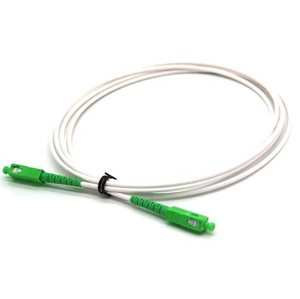
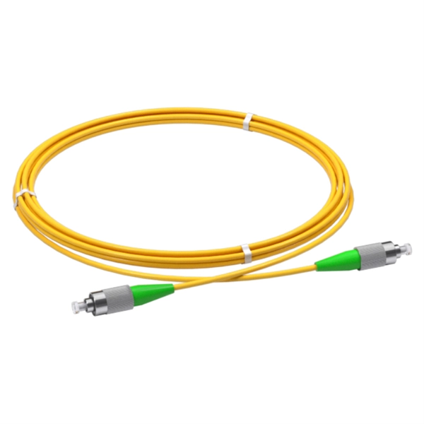
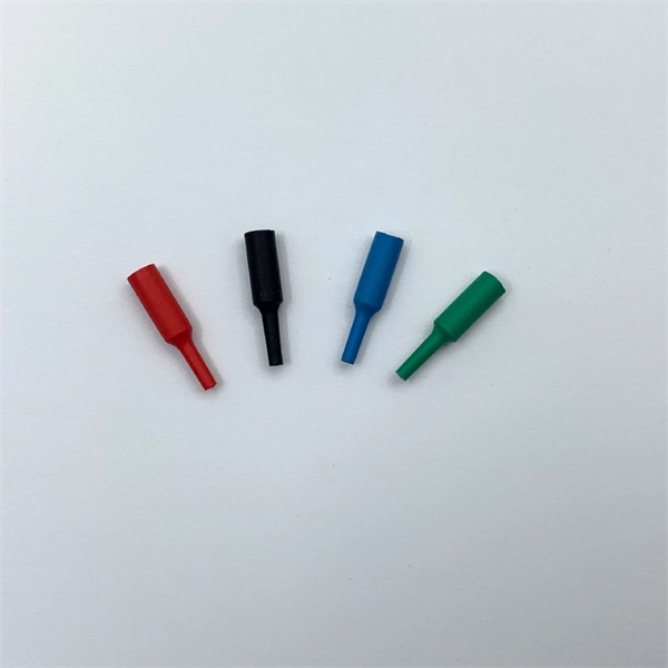
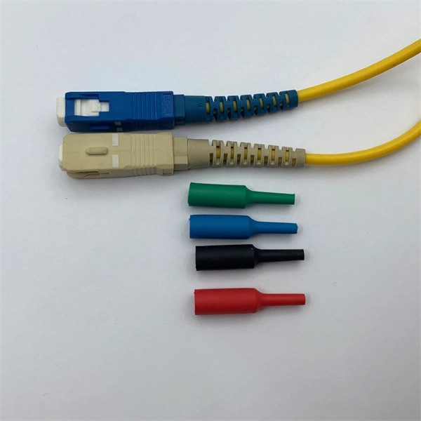
The answer has to do with the connector endface polish, or the angle of connection, and the good news is connectors also follow industry-standard color codes. Fiber connectors are often used as the terminations of optical fiber cables to provide non-permanent connections between fiber-coupled devices (a kind of removable fiber joints). They are used in a similar manner as electrical connectors. This allows for quickly connecting and disconnecting of fiber optic cables without splicing. The connector features a ferrule, the connector end piece that holds and secures the fiber and aligns it for light. The fiber connector is called a fiber optic or optical fiber connector. A link's transmit signal (Tx) must match its corresponding receiver (Rx) at the other end. Although it may seem obvious, fiber optic polarity is a frequent source of confusion and. Fiber optic patch cables consist of the connectors on the ends of the fiber cable. The options on these cables dictate the fiber type, connector type, polarity, and polish type. The fiber types are SMF (Single-mode fiber) and MMF (multimode fiber). The most common connector types are LC, SC. The fiber connector types, sometimes referred to as terminations, link fiber optic cables together through terminals, switches, adapters, and patch panels, by bridging the gap between their internal glass fibers that transmit the data down the length of the cable. The ferrule, a cylindrical.
[PDF]
Prices typically range from about $0. 50 per foot for fiber optic cable and basic installation, depending on indoor vs outdoor routing, distance, and terrain. Commercial building installations with 100-200 network drops generally range from $15,000 to $30,000. Single-mode fiber costs less per foot than multimode fiber, but it requires more. Buyers typically see a wide range in fiber cost per foot depending on cable type, installation method, and terrain. The main cost drivers include cable type (single-mode vs multimode), whether the run is indoors or outdoors, trenching or direct burial requirements, and labor time. This guide presents cost ranges in USD and highlights how per-foot pricing translates to total project costs for typical. The Fiber Broadband Association has partnered with Cartesian to research the cost of deploying fiber and provide insight on how these costs are evolving over time. In preparing this second edition of the Fiber Deployment Cost report, Cartesian gathered inputs from a wide variety of firms building. 1) Proofing and Placement - Per foot pricing for proofing and placement of approximately 1,856,332 ft (351. 864F Prysmian non-armored ribbon cable (24 Fibers per ribbon) into existing empty. conduit (price includes the provision of redline documentation, fiber cable. Buyers typically pay for the cable itself, termination hardware, and professional installation. The following guide outlines typical costs, with practical ranges in USD.
[PDF]
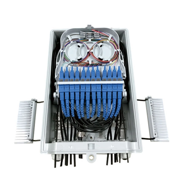
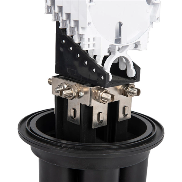
Main Purpose: 6-core fiber optic distribution box, widely used in FTTH project, easy to construct and provide good protective operation. Fiber optic terminal junction boxs are designed to provide a safe and organized solution for managing fiber optic cables in indoor and outdoor. FBR-11606 Fiber-Optic Distribution Box, 6-Core is a high quality product by Bud Industries used for electronic enclosure applications. The HTB8009 6 Ports FTTH Termination Box is a compact, multi-functional distribution enclosure specially designed for final fiber termination at the user end in fiber-to-the-home (FTTH) applications. Built from UV-resistant ABS material, the box combines durability with a sleek form factor, making. The structure of the product is compact, which can meet the needs of various optical cable installation, convenient construction and reliable sealing. Water-proof design with IP65 portection level. Integrated with splice cassette and cable management system. The type of installation for 6 core distribution box is wall-mounted. The entry size of the. Max. Capacity Gcabling is a leading fiber box manufacturer & supplier. We can manufacture and supply a wide range of fiber termination boxes with 20+ years of experience.
[PDF]
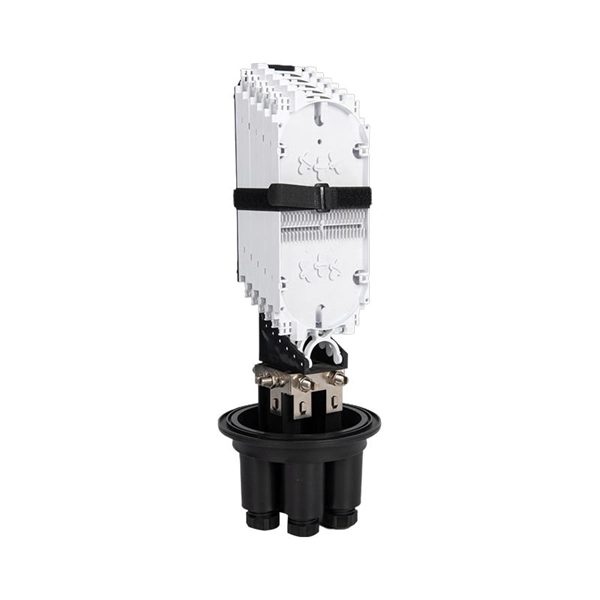
The fiber optic distribution box accomodates up to 6 core fibers and supports outdoor applications within FTTH network system. The type of installation for 6 core distribution box is wall-mounted. The entry size of the drop cable is perfectly designed to accommodate 2x3 millimeters. Serves as a critical termination and distribution point in FTTH networks, offering mechanical protection for fiber optic connections. Ideal for both indoor (residential buildings, offices) and outdoor (exterior walls, utility areas) environments, ensuring durability in diverse conditions. The enclosure supports fiber splicing, splitting, and distribution within a single compact unit, ensuring organized cable routing and secure fiber. [Flexible Flip Board Design] The rotatable flip board allows for up to 180 degrees of flipping, enabling easy angle adjustments during use. [Robust Material] Constructed with abs material, this fiber distribution box offers excellent toughness, strength, wear, and impact. [Minimal Optical Loss]. FBR-11606 Fiber-Optic Distribution Box, 6-Core is a high quality product by Bud Industries used for electronic enclosure applications. It's easy to splice, split and manage the fiber in the box. FDB can provide solid protection and easy maintenance for FTTx network construction.
[PDF]
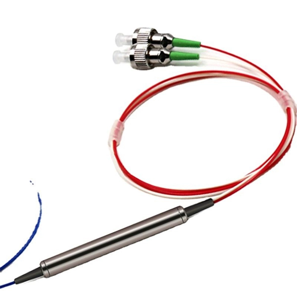
Optical splitters enable a signal on an optical fiber to be distributed among two or more fibers. Since fiber splitters contain no electronics nor require power, they are an integral component and widely used in most fiber-optic networks. A fiber optic splitter is a passive optical component that divides a single incoming optical signal into two or more outgoing signals, or combines multiple incoming signals into one. Unlike active devices (which require power), splitters operate without electricity, relying solely on the physics of. Optical cables, also known as fiber optic cables, consist of thin strands of glass or plastic fibers surrounded by a protective casing. These fibers transmit data as light signals, which are converted into electrical signals at the receiving end. The benefits of optical cables are numerous. A fiber-optic splitter, also known as a beam splitter, is based on a quartz substrate of an integrated waveguide optical power distribution device, similar to a coaxial cable transmission system. Its primary role is in Passive Optical Networks (PON), which are the foundation of. A fiber broadband provider typically determines and overall split ratio for the network, such as 1x32 or 1x64, and uses combinations of splitters to meet that ratio with each PON port. 1x32 splits were common in North America for G-PON architectures. As XGS-PON continues to be adopted, some service.
[PDF]
The projected fiber optic splicer job growth rate is 6% from 2018-2028. About 13,600 new jobs for fiber optic splicers are projected over the next decade. — (September 22, 2025)—Today the Fiber Broadband Association (FBA) and NCTI, a leading broadband and network training solutions provider, unveiled the results of a joint workforce preparedness survey. The findings have been published in a paper titled, “Employer Workforce. The fiber optic splicer market is experiencing robust growth, driven by the expanding global telecommunications infrastructure and the increasing demand for high-speed internet connectivity. The market's Compound Annual Growth Rate (CAGR) is estimated at 7% for the period 2025-2033, indicating a. Government broadband funding is flowing, but the technicians and engineers to build fiber networks don't exist in sufficient numbers. Telecoms are getting creative with recruiting. The Bipartisan Infrastructure Law allocated $42. 5 billion for broadband deployment through the BEAD program. State. Data-driven look at fiber optic and broadband technician careers, including the 178,000-worker shortage driven by $42. 5B in federal broadband investment, salary data, certification paths, and why this may be the best-timed trade career in a generation. Fiber network deployments in the US, while hitting a bit of a slowdown, are proceeding apace and will ramp up significantly as grants start.
[PDF]
This video provides a step-by-step guide on how to efficiently install optical splitter into a fiber terminal box, demonstrating a professional and reliable deployment for optical distribution network solution ( https://www. com/c/optical-distribu. We'll also share tips to minimize signal loss and ensure optimal performance. What Is a Splitter and Why Cascade Them? A splitter divides a single input signal into. When employing the first-level splitting method in a residential network, optical splitters offer flexibility for indoor or outdoor installation. Indoor options encompass locations like the community's central computer room, building's weak current well, or floor wiring box. Optical cables can be. If you have fiber optic cable inside your home, it is possible to install a cable into the home input then split the signal so you can connect the signal to two different television hookups. Insert one end of the fiber optic cable into the "In" port accessible through your wall. The splitter box contains a splitter, which is a passive optical device that divides the incoming light signal. How to install and use fiber optic cable splitter? In fact, the installation of the fiber optic cable splitter is very simple, because it is already a cable terminal product, mainly to see whether it is with a fiber connectors or not, and the packaging type. For example, plc splitter without.
[PDF]
This paper aims to elucidate recent advancements in fiber-optic sensors across different domains, specifically in health, smart home, and smart industry. It particularly emphasizes their integration with various technologies such as machine learning (ML) and the Internet of. If 5G is the neural conduction of the digital age and AI the super brain, fiber sensing serves as the quietly growing peripheral nerves. In 2023, a group from California Institute of Technology, collaborating with Google, achieved the world's first commercial submarine cable-based second-level. Fiber optic sensing has emerged as a cornerstone of modern photonics, enabling high-precision, real-time monitoring in harsh and remote environments. Recent breakthroughs in materials science, laser technologies, and signal demodulation algorithms have expanded the frontiers of this field, driving. Fiber optic sensors utilize optical fibers to measure various physical and chemical properties such as temperature, pressure, strain, and even the presence of specific substances. This. Fiber optic cables form the basis of the infrastructure that provides the high speed, low latency and large data capacity required by IoT. What is IoT and How Does It Work? The internet of things (IoT) is a network where smart devices and sensors communicate with each other over the internet.
[PDF]
We terminate fiber optic cable two ways - with connectors that can mate two fibers to create a temporary joint and/or connect the fiber to a piece of network gear or with splices which create a permanent joint between the two fibers. Proper connection of fiber optic cables is essential to harness these benefits fully, as even minor errors can lead to significant performance issues like signal loss. These terminations must be of the right style, installed in a. Running fiber internally involves extending this high-speed link from the service entry point to a centralized location, such as a dedicated media closet or network rack. This DIY effort is undertaken to maximize performance, improve aesthetics, or relocate the Optical Network Terminal (ONT) to a. In this video, we'll guide you through preparing and terminating fiber optic cables using SimplyFiber products, known for their high quality, ease of use, and reliability. more Audio tracks for some languages were automatically generated. Two types of splices are used in fiber optic cabling one is Mechanical the other is Fusion. Whether you're installing a new network, expanding an existing one, or. But here's the thing: how you connect fiber optic cable really matters. A shaky connection means weaker signals, dropped streaming, or slow uploads. Get the hookup right, and you'll enjoy streaming, gaming, and video calls without interruptions.
[PDF]
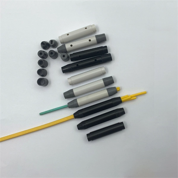
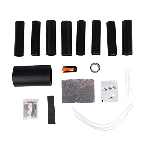
The core principle of fiber optic splicing is to achieve low-loss, high-strength junctions between fiber ends. This involves three key steps: preparation, alignment, and bonding. Let's break it down technically:. At the core of this system's precision and reliability are Fiber Optic Splice Boxes—the unsung heroes that house and protect the delicate junctions where fiber cables are joined. The integrity of these enclosures is paramount to network performance. This guide optimizes the original text by delving. A splice box (also known as splice distributor) is a housing in which fiber optic cables begin or end. Key Functions Typical Applications ZION FTB Highlights In essence: The Fiber Terminal Box is an end-user termination device for small-scale distribution. ■ What Is a Fiber. Fiber optic cables are the lifeline of modern telecommunications, delivering high-speed data with minimal loss. However, installing and maintaining these networks requires seamless connections between fiber segments—a process known as fiber optic splicing. Understanding how it works is essential for anyone interested in telecommunications or network infrastructure. Essential for mending faults or scaling networks, splicing underpins the backbone of contemporary communications. In this comprehensive guide.
[PDF]
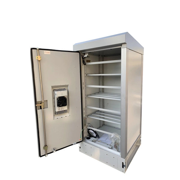
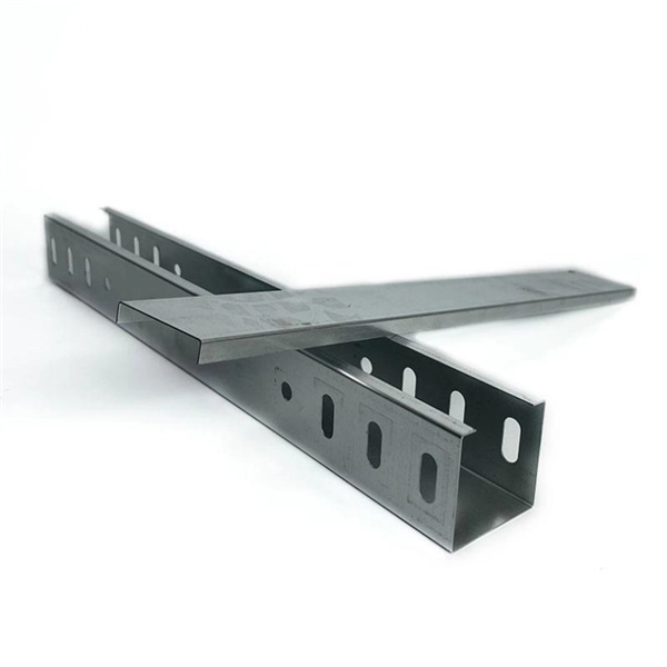
This complete guide explores everything you need to know about ODFs — from their structure, types, and key components, to installation best practices and modern design trends. Whether you're building a central office, data center, or FTTx distribution network, understanding the right ODF. In modern data centers and enterprise networks, Optical Distribution Frames (ODF) serve as the backbone for organizing, terminating, and managing fiber optic connections. This article explores the types, components, applications, installation, and maintenance best practices, providing a. An Optical Distribution Frame (ODF) is the central hub for fiber splicing, termination, patching, and cable protection in modern optical networks. As data centers, enterprises, telecom operators, and smart-building infrastructures deploy increasingly dense fiber links, ODFs provide the structured. Achieve successful cable management, handle high amounts of fiber cable and add density to fiber frames with the new DCX Optical Distribution Frame (ODF) System which features innovations like flippable cassettes, modular frame design and multiple configuration options. The ODF System Components. Optical distribution frames (ODFs) are an all-important network element at the heart of a fiber network. They provide efficient fiber optic management, connectivity, and protection.
[PDF]
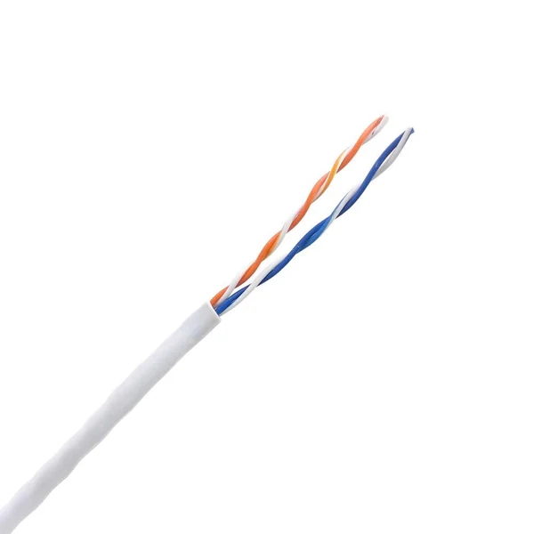
The short answer is no - RJ45 connectors are designed for electrical Ethernet signals, while fiber optics transmit light pulses through glass or plastic. However, modern networks often combine both technologies. With the launch of the new Wi-Fi 7 routers BE800 and BE900, our home routers have begun to utilize the high speeds that come with added SFP+ Compatibility. The SFP+ port is a high-speed optical-to-optical signal conversion port, mainly used for 10G Ethernet and Fiber Channel network applications. A. Small Form-factor Pluggable (SFP) is a compact, hot-pluggable network interface module format used for both telecommunication and data communications applications. Think of it as the “translator” for your network equipment, converting electrical signals into optical signals. SFP (Small Form-factor Pluggable) modules, also known as mini-GBICs (Gigabit Interface Converters), are commonly used in network switches and routers to provide flexible and modular network connectivity options. These types of ports can be used with various transceivers thereby allowing the system administrators to customize connectivity according to their network topology. SFP modules and DAC cables are used inside SFP28/SFP/SFP+ slots on UniFi or client devices. These slots allow for versatile connectivity options using different types of cabling. SFP+ and SPF28 DAC Cables: Establishing 1/10/25 Gbps connections over short distances, e. between devices in the same.
[PDF]
For singlemode fiber, the loss is about 0. 5 dB per km for 1310 nm sources, 0. 5 dB/km at either wavelength for outside plant max per EIA/TIA 568)This roughly translates into a loss of 0. 1. To be able to judge whether a fiber optic cable plant is good, one does a insertion loss test with a light source and power meter and compares that to an estimate of what is a reasonable loss for that cable plant. The estimate, called a "loss budget" is calculated using typical component losses for. Manufacturers provide a fiber loss factor in dB per kilometer. Total fiber loss is calculated by multiplying the distance by the loss factor, considering the actual cable length. 25 dB/km (@1550nm) and 0. Understanding where those losses come from, and how to calculate them, is essential for designing a link that actually works. The decibel is. A loss budget in fibre optics is a detailed accounting of every potential source of signal attenuation (loss) in a fibre optic link. By accurately calculating and managing loss budgets, engineers and technicians can guarantee that optical signals reach their destination with enough power to be. After measuring the loss of a fiber link, you now have to determine if that fiber link loss is acceptable or not. Here are the details and instructions about each field and how they contribute to the calculation: 1. Attenuation Coefficient (dB/km): This value represents the inherent signal loss per kilometer of.
[PDF]