In this guide, we'll walk you through the entire process of preparing fiber optic cable for splicing and termination to fiber connectors. We'll explore the necessary tools, safety precautions, and step-by-step procedures for cable connectors, mechanical and. This article will guide you through the necessary tools, materials, and methods on how to connect fiber optic cables effectively, ensuring you achieve optimal performance from your fiber optic network. Have a network installation project? Fiber Optic Cables: The primary medium for your connections. There are many types of fiber optic connectors, including SC, LC, FC, ST, D4, MU, MT/MPO, etc. These connectors can be divided into single-mode and multi-mode fiber optic connectors according to their structure and purpose. Fiber optic connectors play an essential role in the realm of optical communication, enabling seamless connections between fiber optic cables. At the heart of any robust fiber optic network lies a crucial process: Preparing a fiber cable for termination of a connector or splice. Whether you're installing a new network, expanding an existing one, or. Fiber optic internet delivers blazing-fast speeds and reliable connectivity, making it a top choice for modern homes and businesses.
[PDF]
This video makes connecting your fiber optic cable to your router a breeze! We'll guide you through the entire process step-by-step, ensuring a smooth and hassle-free experience. Our Experts are helping user's, who are facing issues with their tech gadgets like. In this guide, we'll walk you through how to connect a fiber optic cable to a router safely and efficiently. Why Use Fiber Optic Internet? Before diving into the setup, let's quickly recap why fiber optics are worth the effort: Lightning-fast speeds (up to 1 Gbps or higher). This comprehensive guide combines industry standards with field-tested practices to ensure you achieve a rock-solid. Setting up a fiber internet connection requires understanding key hardware components and following a specific connection sequence to establish your home network. This guide details the necessary physical and digital steps to connect your fiber line and activate your internet service. The fiber. Connecting a fiber optic cable is straightforward, but requires care. The process depends on the equipment you're connecting. Here's a general guide and examples based on common scenarios: This usually involves connecting the fiber cable from your internet service provider (ISP) to your home. In this article we'll break down how fiber internet is installed - from the network fiber drop outside your house to the in-home setup with your router and gateway - and what you should expect at each stage.
[PDF]
This article explains eight of the most important global fiber and cable standards — ITU-T, IEC, TIA, ISO/IEC, and Telcordia — covering their scope, applications, and why they matter in real-world deployments. Fiber optic network design refers to the specialized processes leading to a successful installation and operation of a fiber optic network. It includes determining the type of communication system(s) which will be carried over the network, the geographic layout (premises, campus, outside plant. Our expert OSP Network Designers in FTTH, FTTx designs and standards enables us to provide top quality services to EPC companies all over the world. For New Network builds, we have experience ranging from Single and Multi-dwelling Units, Commercial Units FTTH Fibre-to-the-Home networks, Outside. Fiber optic networks are built on well-defined standards that ensure quality, performance, and interoperability. 8 billion in 2022 and is expected to reach $11. This is the dominant broadband access technology across half of OECD countries today. Source: OECD broadband.
[PDF]
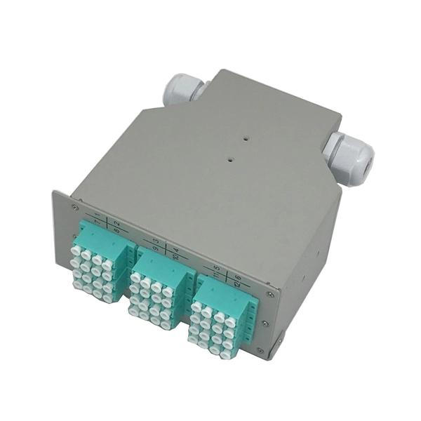
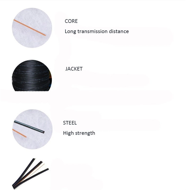
Fiber optic patch cables work based on the principle of total internal reflection. The core of the fiber acts as a waveguide, allowing light to travel through it by bouncing off the cladding. The light signals are transmitted through the core in the form of pulses, representing. The functioning of a fiber optic patch cord relies on its construction. It consists of a core with a high refractive index, enveloped by a coating featuring a lower refractive index. This assembly is fortified using aramid yarns and encased within a protective jacket. The core's transparency. Optical Fiber Patch Cords are designed to connect various optical devices and network components, facilitating high-speed data transfer across significant distances without degradation. They are an essential component of modern networking systems, enabling high-speed and reliable data transfer. They act as the critical link for interconnecting devices like optical switches, servers, and distribution frames. A bulk (multi-strand) fiber cable enters the patch panel and then each fiber strand is separated into individual strands or pairs of strands. This design allows the light to travel.
[PDF]
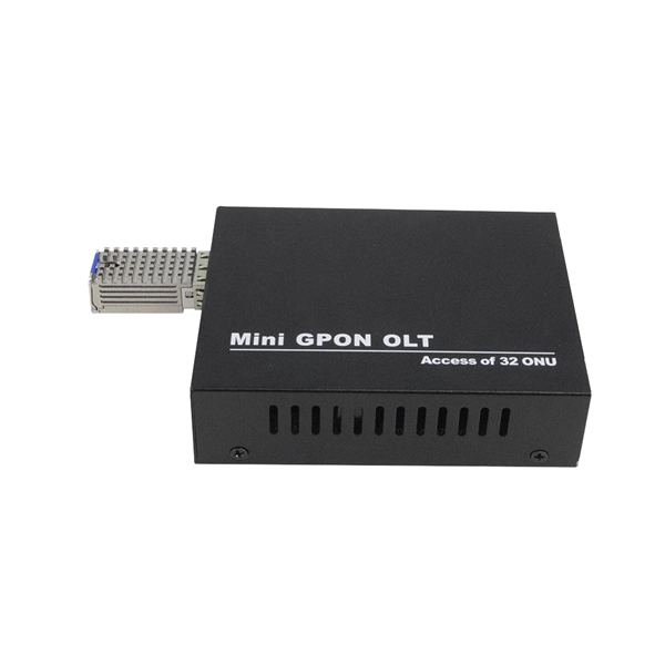
Insert a compatible SFP transceiver into the converter's port, making sure it matches the network's media type and speed. Then, connect one end of the fiber cable to the transceiver and the other to the appropriate port on a switch, router, or another media converter. Fiber media converters translate copper's electrical signals into fiber's optical signals, and back again. This allows networks to extend beyond the 100 m copper limit while gaining higher bandwidth and resistance to electromagnetic interference. In the illustrated setup, each LAN links to a. A fiber media converter is a networking device that allows you to convert a signal from one medium to another. This allows you to connect devices that use different types of cabling, such as a computer. While fiber optic ports are becoming increasingly common on networked electronics, the majority of connected devices still rely on RJ45 twisted pair connections. To help bridge the copper-fiber divide, media converters and transceiver modules (also known as SFPs or mini-GBICs) are often required. Use Fiber Media Converter in Your Network Media converters today are widely deployed in all. It is a device used to convert fiber optic cables to Ethernet cables to provide better connectivity. It is necessary to convert fiber optic signals to Ethernet signals because many network devices can only communicate with Ethernet signals. Fiber optic cables are known for the unmatched speed.
[PDF]
While fiber internet doesn't require a modem, you still need a router to distribute the connection across your network. Your router works hand-in-hand with the ONT, taking the internet signal and spreading it wirelessly or through Ethernet cables to all your connected devices. When setting up an enterprise network, especially one with fiber optic internet, two pieces of hardware often come up: the router and the Optical Network Terminal (ONT). While both are vital for connecting your business to the internet, they perform distinct and separate jobs. Understanding the. This device connects your business to your fiber ISP by converting the signals sent over fiber optic cables into electronic data your network devices can actually use. Do You Need a Modem for Fiber Internet? The short answer is no – fiber internet doesn't need a modem. Your ONT handles signal. Verizon Fios Internet Service uses state-of-the-art fiber-optic technology to deliver broadband internet access to your business. Instead, it uses an ONT. Many people have used cable or DSL internet in the past, so they are used to having a modem. However, not all routers can create a Wi-Fi network if it's not fiber-ready. If your existing router meets specific Wireless Standards requirements, you may be able to use it with fiber internet. Therefore, the ONT has one or more ports for routers, computers, or other user devices to connect to.
[PDF]
At its core, a fiber optic splitter relies on the principles of light reflection, refraction, and waveguiding to divide signals. Its design varies by type, but the underlying mechanism involves manipulating light to distribute its power across multiple output ports. A fiber optic splitter is a passive optical component that divides a single incoming optical signal into two or more outgoing signals, or combines multiple incoming signals into one. It plays a vital role in optical fiber communication systems, especially in passive optical networks (PONs). This type of device plays an important role in passive. many aspects of a Fiber to the X (FTTx) network. Splitter architectures can impact fiber counts, splicing needed, numbers of fiber needed, and the customer on-boarding process. conversations and confusion in the industry. of splitting architectures. A “splitter” is a power splitter. A splitter is. Understanding Fiber Optic Splitters: Principles, Parameters, Types, Applications, and Future Trends 1. They are devices that split an incident light beam into several light beams at certain splitting.
[PDF]
They are backward compatible with existing network equipment and provide close to three times the bandwidth of traditional 62. 5/125 multimode fibers. 10 Gigabit is rated for distances up to 300 meters using 850nm Vertical Cavity Surface Emitting Lasers (VCSEL). 10Gig fiber optic. Fiber optic patch cable, often called fiber optic patch cord or fiber jumper cable, is a fiber optic cable terminated with fiber optic connectors on both ends. It has two major application areas: computer work station to outlet and fiber optic patch panels or optical cross connect distribution. This duplex multimode fiber optic patch cable features LC to LC UPC connectors and uses OM5 50/125µm laser-optimized multimode fiber, designed for ultra-fast data transmission and future-ready network scalability. The lime green jacket identifies it as OM5 fiber, optimized for Short-Wavelength. Connect high-speed data networks and power outlets to switches, routers and servers, even in high density environments. With 10GB/100GB Ethernet speeds up to 300M at 850nm and backwards compatibility, this laser-optimized multimode fiber is a great solution, for your office or campus. Made For:. Learn why IT Pros trust StarTech. com for performance connectivity accessories. As networks move to higher speeds and higher density, choosing the right fiber optic patch cords becomes critical to the reliability of your system. Understanding the various technical.
[PDF]
This guide covers the essential tools and step-by-step procedures for low-loss fiber optic cable repair. Fiber optic cable is strong, reliable and built for long-term performance, but it still needs to be handled correctly during installation. Most fiber damage does not come from normal operation after the system is live. It happens during installation, when excessive pulling force, tight bends. In today's hyper-connected world, fiber optic cables serve as the lifelines of high-speed data transmission, powering everything from global telecom networks to local FTTH (Fiber to the Home) systems. This article explores recommendations for pulling and installing fiber optic cable. Most fiber optic cables boast a pull strength of 100 – 200. While fiber optic cables are generally quite durable when correctly handled, defects and damage can happen. Cracks and breaks are of particular concern since they can cause data transmission to cease altogether. When these failures occur, they can cause costly network downtime. The Future Ready Solutions Tools & Test. Fiber optic cable cuts can be alarming, especially with problems like signals being dropped, internet interruptions, or even network failures. However, you don't need to panic! It can still be fixed. If you have the right tools and knowledge, you can definitely find the solution. Whether you have a.
[PDF]
In this detailed video, we'll walk you through the fiber optic pigtail splicing process — from preparation to final testing. Executive Summary: A fiber optic pigtail is one of the most commonly specified yet least understood components in structured cabling. If you're new to fiber optics or want to enhance your technical skills, this guide will help you understand how to splice fiber pigtails safely and efficiently. --- 🔧 In. Field-terminating connectors is a meticulous, high-pressure process where even a tiny mistake can force you to cut the fiber and start all over again. This is exactly why most professional installers have moved away from field-termination and toward splicing. The most efficient way to terminate a. A fiber pigtail is typically a fiber optic cable with one end factory pre-terminated fiber connector and the other exposed fiber. Compared with quick termination or epoxy and polish connections placed on the field. Fiber pigtails are simple in appearance, yet essential in function. They are the bridge between fiber optic cables in the field and the equipment or patch panels that manage them. By combining factory-installed connectors with spliced bare fiber, pigtails ensure that network installers can create. Fiber optic pigtail offers an optimal way to joint optical fiber, which is used in 99% of single-mode applications.
[PDF]
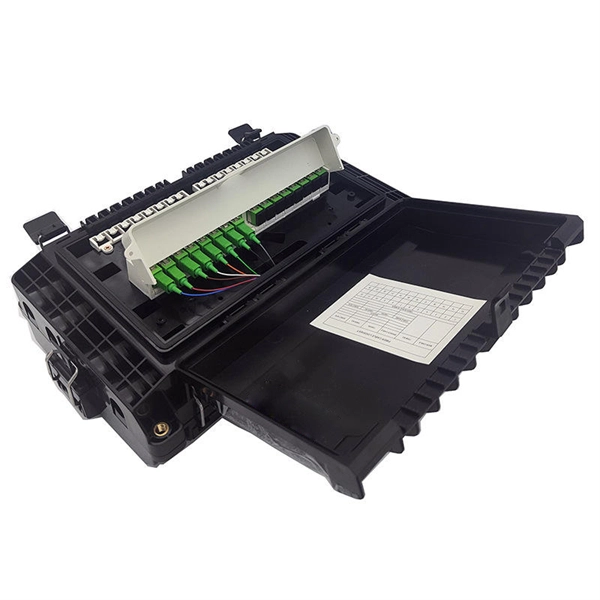
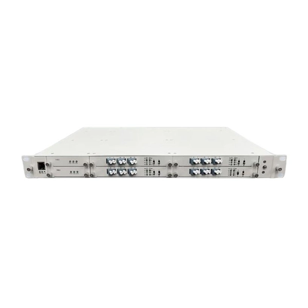
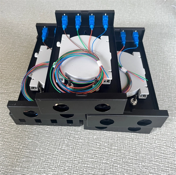
Join our mailing list and receive free updates every month! 24 Core IP68 Splice Enclosure with 2 x 12 Way Splice Trays (185 x 260 x 70) 2 ports in 2 ports out If you require a bespoke product please click here to contact us with your requirements for a quote. CD-24F-FS-W 24 Fibers Splice Tray provides secure organization and protection for up to 24 fusion splices, ensuring reliable performance in FTTx, data center, and enterprise networks. Its compact capacity and stackable design make it ideal for small-scale or distributed fiber management. These fiber splice trays, adapter panels and cable fan-out kits can accept up to 24 fibers. Made by AFL, Corning, Leviton, Pandit and other manufacturers. RLH Industries Outside Plant Fiber Splice Closure provides reliable and flexible installation for outdoor applications. The compact size and high quality construction allow for installation in both underground and aerial environments. The case lid is hinged for correct alignment and is secured with. Check each product page for other buying options. Price and other details may vary based on product size and color. Need help?. ZIP code to view pricing. ZIP code to. Whether you need fusion splicing for permanent, ultra-low-loss connections or mechanical splicing for rapid field deployment, our certified technicians deliver factory-quality results on every job — from hyperscale data centers and carrier-grade telecom networks to enterprise campus infrastructure.
[PDF]
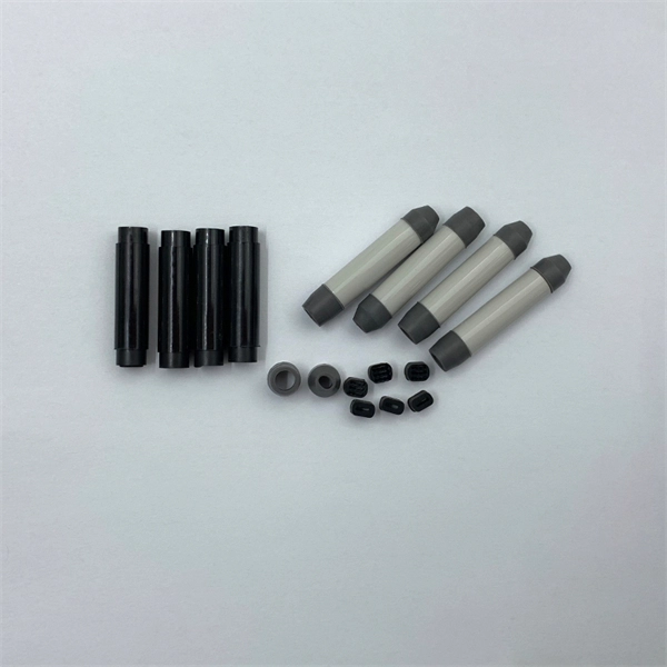
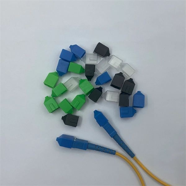
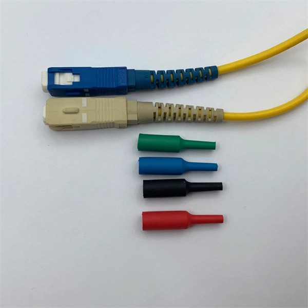
A2: According to EIA/TIA-598, the fiber optic cable color code defines the jacket color codes for different fiber types (SMF or MMF). Fiber optic color codes provide the essential identification framework that enables fiber technicians and network professionals to manage complex optical network installations efficiently. This standardized fiber optic color coding system helps prevent costly connection errors while dramatically. Understanding fiber‑optic color codes is essential for any technician tasked with installing, maintaining, or troubleshooting modern fiber networks. By adopting the TIA/EIA‑598C standard, you gain a universal “language” of colors that speeds identification, reduces miswiring, and enhances safety. The TIA-598-D standard defines a standardized color-coding system that engineers and technicians rely on to identify different types of fiber optic cables, connectors, and individual fibers. Designed for durability and reliability, the sleeves are constructed with an inner EVA meltable adhesive tube, and a polyolefin heat shrink outer tube. The strength member within the sleeve is made of. Color codes are used in fiber optics to identify fibers, cables and connectors. This coding system is the EIA/TIA-598 standard developed by the Electronic Industries Alliance (EIA) and the Telecommunications Industry.
[PDF]
Passive media components such as cables, cable splices, and connectors cause attenuation. Although attenuation is significantly lower for optical fiber than for other media, it still occurs in both multimode and single-mode transmissions. Two fundamental mechanisms cause attenuation inside the fiber itself: absorption and scattering. These are intrinsic to the glass, meaning they exist even in a perfectly manufactured, perfectly installed fiber. Scattering is the bigger factor at the wavelengths most networks use. The silica glass. Optical attenuation is the gradual loss of flux (light intensity) as an optical signal travels through a fiber. Measured in decibels (dB), it's the logarithmic ratio of the output power to the input power. Every network has a "loss budget". F iber optic networks rely on the efficient transmission of light signals to deliver high-speed data over long distances. However, various factors can cause signal degradation, leading to performance issues and reduced network reliability. You may see slower speeds and less steady connections when signal loss goes up. Things like impurities in the fiber core and reflections at the core-cladding edge cause this drop. This can be due to a variety of factors: scattering and absorption, intrinsic. Signal attenuation in fiber optics is a key concept in telecommunications. It affects how far a signal can travel without losing.
[PDF]
The most common operating principle of a directional fiber coupler is evanescent wave coupling in a configuration where two fiber cores come close to each other. Such a device can be made by heating two bare fibers such that the glass begins to melt and the fibers fuse together. The tutorial has the following parts: Figure 1: A 2-by-2 fiber coupler. When using fiber optics, one often needs to use fiber. Fiber optic couplers, also known as fiber optic splitters, are devices used to split or combine optical signals in fiber optic networks. They play a crucial role in various applications, such as telecommunications, data centers, and fiber-to-the-home (FTTH) installations. In simple terms, they serve as the 'traffic managers' of the light that carries information within the fiber optic network. It functions by dividing a single incoming light path into multiple outgoing paths, or by combining light from several input paths into a single output fiber. This capability is fundamental. This tab provides a brief explanation of how we determine several key specifications for our 1x2 couplers. 1x2 couplers are manufactured using the same process as our 2x2 fiber optic couplers, except the second input port is internally terminated using a proprietary method that minimizes back.
[PDF]
For singlemode fiber, the loss is about 0. 5 dB per km for 1310 nm sources, 0. 5 dB/km at either wavelength for outside plant max per EIA/TIA 568)This roughly translates into a loss of 0. 1. To be able to judge whether a fiber optic cable plant is good, one does a insertion loss test with a light source and power meter and compares that to an estimate of what is a reasonable loss for that cable plant. The estimate, called a "loss budget" is calculated using typical component losses for. Manufacturers provide a fiber loss factor in dB per kilometer. Total fiber loss is calculated by multiplying the distance by the loss factor, considering the actual cable length. 25 dB/km (@1550nm) and 0. Understanding where those losses come from, and how to calculate them, is essential for designing a link that actually works. The decibel is. A loss budget in fibre optics is a detailed accounting of every potential source of signal attenuation (loss) in a fibre optic link. By accurately calculating and managing loss budgets, engineers and technicians can guarantee that optical signals reach their destination with enough power to be. After measuring the loss of a fiber link, you now have to determine if that fiber link loss is acceptable or not. Here are the details and instructions about each field and how they contribute to the calculation: 1. Attenuation Coefficient (dB/km): This value represents the inherent signal loss per kilometer of.
[PDF]