In network cabling, outdoor connections generally use fiber optic cables. When these optical fibers are installed or laid out, a Fiber Termination Box, or FTB, is used to distribute and protect the optical fiber link.
[PDF]
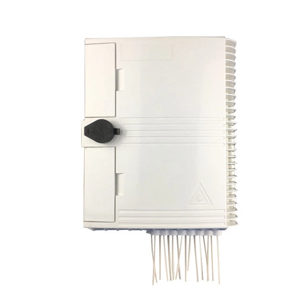
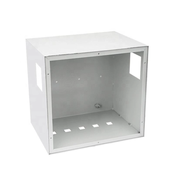
A fiber optic termination box is an enclosure designed to terminate incoming optical fiber cables and distribute optical signals to drop cables or patch cords. It integrates fiber splicing, adapter management, and cable protection in one compact unit. What Is the Role of a Fiber Optic Terminal Box in FTTH? When most teams plan an FTTH rollout, they obsess over feeder routes, splitter ratios, and ONT models—but the handoff point where glass meets the living space is often under-specified. That handoff lives inside the Fiber Optic Terminal Box. In. ■ What is a Fiber Access Terminal (FAT)? A Fiber Access Terminal (FAT), also known as a Fiber Access Terminal Box (ATB) or Fiber Distribution Terminal (FDT), is a key component found in optimized fiber optic access networks for FTTH implementations. It is the junction point between the distribution. This guide explains what a fiber optic termination box is, how it works in practice, where it is typically installed, and how to choose the right model for different network environments. They play a critical role in managing. A fiber optic terminal box (FTB )is a box that protects the fiber optic cable and the fiber optic pigtail fusion at the terminal of the fiber optic cable. It is used for the connection and termination of fibers and to protect the spliced fiber.
[PDF]
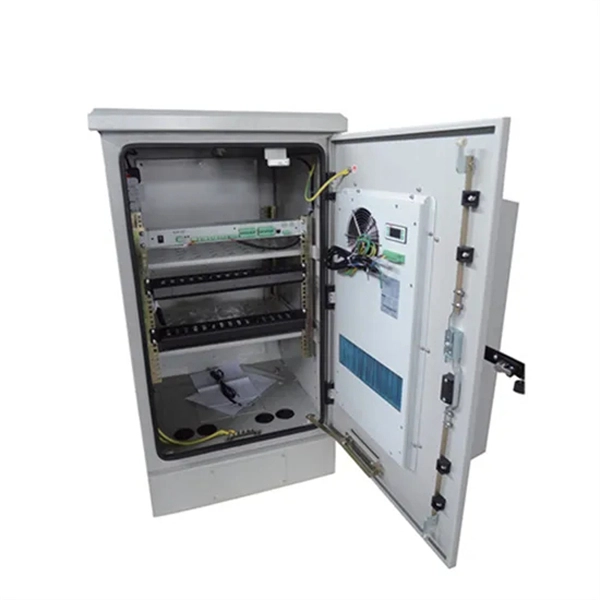
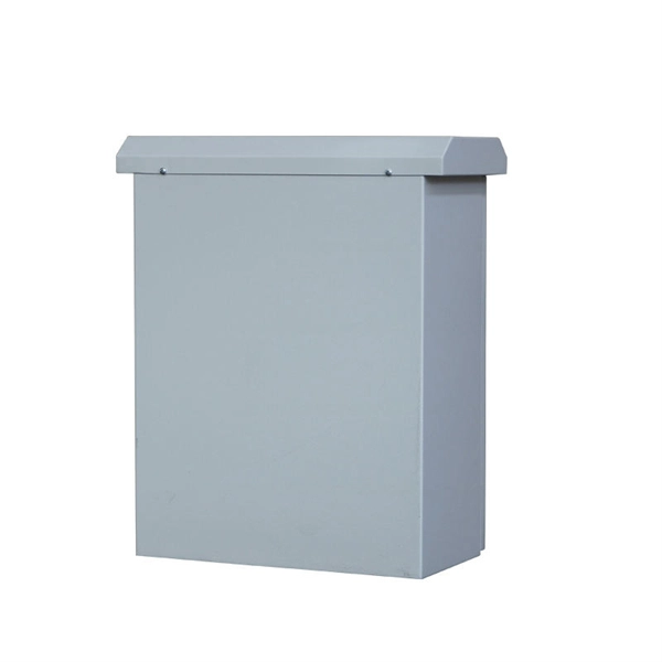
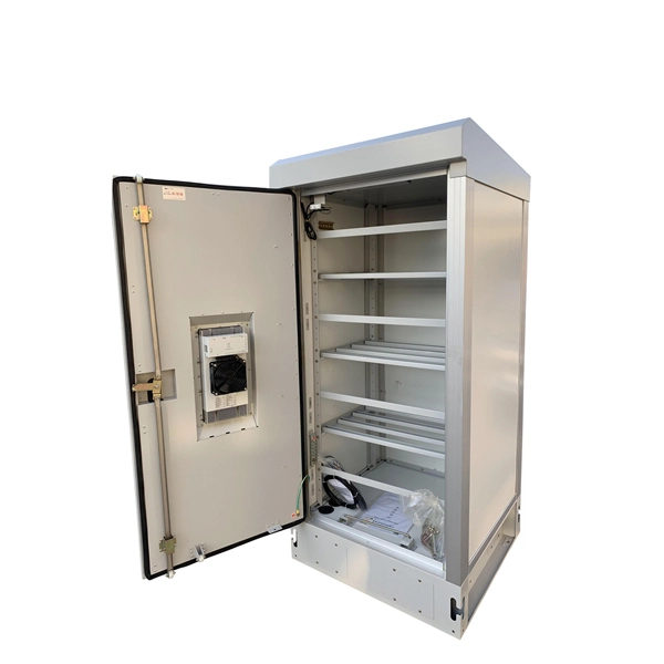
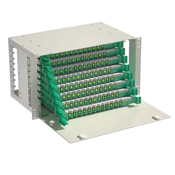
Fiber distribution box, also known as fiber optic distribution frame, is an essential component in fiber optic communication networks. It plays an important role in organizing, managing, and protecting fiber optic cables, ensuring reliable and efficient network operations. With features like IP68 waterproof ratings, fast connectors, and hardened adapters, distribution boxes enhance data transmission by offering proper termination points and environmental protection. It provides a secure space where incoming fiber optic cables from the provider's network are. A fiber distribution cabinet is a key component in modern fiber optic networks, designed to manage, protect, and distribute optical fibers efficiently. It serves as a central point where fiber cables are terminated, spliced, and organized for further connection to end users. The distribution box provides.
[PDF]
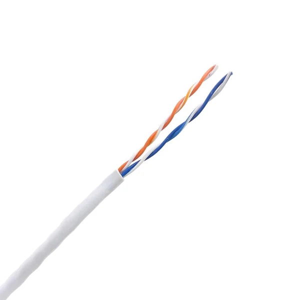
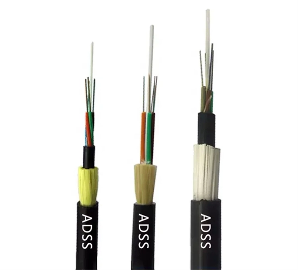
Fiber optic cables are, like their name suggests, a cable that uses light, rather than electricity to transmit information. They're made from silica glass fibers about the same width as a human hair, which all.
[PDF]
This video provides a step-by-step guide on how to efficiently install optical splitter into a fiber terminal box, demonstrating a professional and reliable deployment for optical distribution network solution ( https://www. com/c/optical-distribu. We'll also share tips to minimize signal loss and ensure optimal performance. What Is a Splitter and Why Cascade Them? A splitter divides a single input signal into. When employing the first-level splitting method in a residential network, optical splitters offer flexibility for indoor or outdoor installation. Indoor options encompass locations like the community's central computer room, building's weak current well, or floor wiring box. Optical cables can be. If you have fiber optic cable inside your home, it is possible to install a cable into the home input then split the signal so you can connect the signal to two different television hookups. Insert one end of the fiber optic cable into the "In" port accessible through your wall. The splitter box contains a splitter, which is a passive optical device that divides the incoming light signal. How to install and use fiber optic cable splitter? In fact, the installation of the fiber optic cable splitter is very simple, because it is already a cable terminal product, mainly to see whether it is with a fiber connectors or not, and the packaging type. For example, plc splitter without.
[PDF]
The core principle of fiber optic splicing is to achieve low-loss, high-strength junctions between fiber ends. This involves three key steps: preparation, alignment, and bonding. Let's break it down technically:. At the core of this system's precision and reliability are Fiber Optic Splice Boxes—the unsung heroes that house and protect the delicate junctions where fiber cables are joined. The integrity of these enclosures is paramount to network performance. This guide optimizes the original text by delving. A splice box (also known as splice distributor) is a housing in which fiber optic cables begin or end. Key Functions Typical Applications ZION FTB Highlights In essence: The Fiber Terminal Box is an end-user termination device for small-scale distribution. ■ What Is a Fiber. Fiber optic cables are the lifeline of modern telecommunications, delivering high-speed data with minimal loss. However, installing and maintaining these networks requires seamless connections between fiber segments—a process known as fiber optic splicing. Understanding how it works is essential for anyone interested in telecommunications or network infrastructure. Essential for mending faults or scaling networks, splicing underpins the backbone of contemporary communications. In this comprehensive guide.
[PDF]
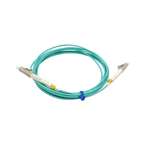
We terminate fiber optic cable two ways - with connectors that can mate two fibers to create a temporary joint and/or connect the fiber to a piece of network gear or with splices which create a permanent joint between the two fibers. Proper connection of fiber optic cables is essential to harness these benefits fully, as even minor errors can lead to significant performance issues like signal loss. These terminations must be of the right style, installed in a. Running fiber internally involves extending this high-speed link from the service entry point to a centralized location, such as a dedicated media closet or network rack. This DIY effort is undertaken to maximize performance, improve aesthetics, or relocate the Optical Network Terminal (ONT) to a. In this video, we'll guide you through preparing and terminating fiber optic cables using SimplyFiber products, known for their high quality, ease of use, and reliability. more Audio tracks for some languages were automatically generated. Two types of splices are used in fiber optic cabling one is Mechanical the other is Fusion. Whether you're installing a new network, expanding an existing one, or. But here's the thing: how you connect fiber optic cable really matters. A shaky connection means weaker signals, dropped streaming, or slow uploads. Get the hookup right, and you'll enjoy streaming, gaming, and video calls without interruptions.
[PDF]
This section provides an overview for fiber optic sensors as well as their applications and principles. Also, please take a look at the list of 18 fiber optic sensor manufacturers and their company ranki.
[PDF]
Underground fiber optic cable installation follows specific standards that govern burial depth, testing methods, installation techniques, and safety requirements. Underground cables are pulled in conduit that is buried underground, usually 1-1. 2 meters (3-4 feet) deep to reduce the likelihood of accidentally being dug up. In extreme cold climates, cables may need to be buried at greater depths where there temperatures are colder and frost penetrates to. The Fiber Optic Association, Inc. (FOA) was founded in 1995 to help develop the workforce to build the fiber optic networks to support a rapid expansion in communications and the Internet. The charter of the FOA was to promote professionalism in fiber optics through education, certification, and. This guide walks through each stage of underground fiber installation—from route planning and conduit selection to splicing, termination, and testing—to help ensure long-term network performance and reliability. These standards, established by organizations like the National Electrical Code (NEC), National Electrical Safety Code (NESC), and. Installing underground fiber optic cables is critical to establishing high speed internet infrastructure that delivers reliable connectivity for businesses nationwide. Unlike traditional copper systems, fiber optic cables require specialized handling techniques and precise installation methods to.
[PDF]
Fiber Connection: Locate the optical port on your router and carefully insert the fiber cable's connector, ensuring a snug fit. Click it into place if it has a locking mechanism. Power Up: Connect the power cords to your router and any additional devices (ONT, media converter) and. Proper connection of fiber optic cables is essential to harness these benefits fully, as even minor errors can lead to significant performance issues like signal loss. This article will guide you through the necessary tools, materials, and methods on how to connect fiber optic cables effectively. Fiber optic internet delivers blazing-fast speeds and reliable connectivity, making it a top choice for modern homes and businesses. However, setting up a fiber optic connection to your router can seem daunting if you're unfamiliar with the process. Before you start, gather the right tools. You don't want to dig around mid-job for something small but essential. Each tool helps you protect the fiber. The process to connect fiber optic cable to router requires careful attention to detail, but I'll walk you through every critical step with the precision and clarity you deserve. The fiber. The process involves a combination of national infrastructure, local engineering, and property-level setup. In this guide, we'll break down the fiber installation process from start to finish and explain key components such as fiber cabinets, flower pods, ducting, and ONT setup. What Is Fiber Optic.
[PDF]

This interactive submarine cable map shows global undersea and underwater fiber optic cables connecting continents and countries worldwide. Explore cable routes, landing stations, system status and infrastructure updates. This visualization shows the growth of the undersea cable network, global internet peering capacity, and the distribution of IP addresses via BGP announcements over time. Use the controls at the top to play the animation or step through year by year. For more details and insights, please read this. Deep Sea Laying System will dominate with a 59. 0% market share, while digital communication infrastructure will lead the application segment with a 64. The offshore fibre optic cable lay market is valued at USD 3. 0 billion in 2025 and is forecasted to reach USD 6. 5 billion by 2035. Fibre-optic Link Around the Globe (FLAG) is a 28,000-kilometre-long (17,398 mi; 15,119 nmi) fibre optic mostly- submarine communications cable that connects the United Kingdom, Japan, India, and many places in between. As digital economies expand and geopolitical tensions shape technological dependencies, undersea cables emerge not. The global Offshore Fibre Optic Cable Lay market size is expected to reach $ 4745 million by 2031, rising at a market growth of 7. 8% CAGR during the forecast period (2025-2031). Offshore Fibre Optic Cable Lay refers to the process of installing fibre optic cables on or beneath the seabed to enable.
[PDF]
This paper provides a systematic introduction to the principle of FP cavity fiber optic sensors based on thin film technology and reviews the applications and development trends of this sensor in various measurement fields. Currently, there is a growing need for precise measurements in both. This is the power of fiber optic sensing, a technology that transforms ordinary optical fibers into the digital world's sensory network. In 2023, researchers turned submarine cables into earthquake warning systems and gave electric vehicles “optical nerves” to prevent battery failures. It aims to provide a comprehensive collection of cutting-edge research that pushes the boundaries of fiber optic sensor technologies, integrating them with emerging trends and. Optical fiber (OF) sensors are critical optical devices with excellent sensing capabilities and the capacity to operate in remote and hostile environments. However, integrating functional materials and micro/nanostructures into the optical fiber systems for specific sensing applications has. The Fiber Optic Sensing Association (FOSA) is dedicated to accelerating the use of distributed and quasi-distributed optical fiber sensing technologies. Fiber optic sensing works by measuring changes in the “backscattering” of light occurring in an optical fiber when the fiber encounters vibration.
[PDF]
This article outlines seven common issues that require professional fiber optic services. Fiber optic troubleshooting is an essential skill for network administrators, technicians, and engineers responsible for maintaining and repairing fiber optic systems. These high-speed, high-capacity communication networks are increasingly replacing copper cables, offering superior performance and. Fiber optic cables are the backbone of modern communications, delivering high-speed data over long distances with minimal loss. However, in real-world installations, whether underground, aerial, or in harsh industrial environments, fiber cables can and do fail. Understanding the common causes of. Fiber optic communication uses pulses of light to transmit data along thin strands of glass or plastic. Because the technology is reliable and supports long distances with higher speeds than other connections, fiber optics have revolutionized the telecommunications industry. However, like any technology, fiber optic systems can encounter issues that affect performance. But before we dive into the actions, it's important to.
[PDF]
The cost to fix a fiber line often hinges on the fault type, distance, and response time, with price ranges reflecting differing crews and materials. Includes crew time for fault locating, splicing, and testing. Includes connectors, fiber patches, splice. Buyers typically see repair costs driven by cable type, damage location, and access challenges. Includes crew time for fault locating, splicing, and. This guide provides a detailed roadmap for locating and fixing fiber optic cable breaks, covering detection techniques, repair methods, and best practices. With CommMesh's advanced tools and solutions, you'll learn how to restore networks seamlessly. Main cost drivers include on-site labor, specialized fusion splicing, testing, and any necessary restoration of network performance. This guide provides practical cost ranges in USD with. Fiber optic cable is the primary media for outside plants, campuses, and LAN backbone infrastructure because it can transmit more data farther. It also comprises the majority of data center switch-to-switch and switch-to-server links that transmit high volumes of data at faster speeds. It's even. When fiber optic cables fail or require maintenance, typical repair costs hinge on incident location, damage severity, and the required equipment. Expect costs to reflect both material needs and labor time, plus any regional price differences.
[PDF]
This paper describes a disruptive continuous monitoring system to detect Corrosion Under Insulation (CUI) risks for every meter of pipeline over large distances. Distributed Fiber Optic Sensing (DFOS) has emerged as a viable non-destructive ATEX-proof solution to detect CUI. ors by depositing metal coatings to the surface of the sensors. Three types of fiber optic sensors were investigated as candidates for corrosion detection: the extrinsic Fabry-Perot interferometer (EFPI), the absolute extrinsic Fabry-Perot interferomete (AEFPI), and the long period grating (LPG). This paper presents a distributed monitoring approach for detection, visualization, quantification, and warning for pipe corrosion using a single-mode telecommunication-grade fiber optic cable as a distributed sensor. The distributed sensor can be deployed on the surface of a pipe to measure. Fiber optic AE sensor was tested due to its anti-explosiveness, fitting to petrochemical plants. Experiment was successful, and one sensor could detect approx. 4,000mm-away corrosion. Our study attempts to detect. Experimental Investigation for Monitoring Corrosion Using Plastic Optical Fiber Sensors Liang Hou 1,*, Shinichi Akutagawa 1, Yuki Tomoshige 2and Takashi Kimura 2 1Department of Civil Engineering, Kobe University, 1 -1, Rokkodaicho, Nadaku, Kobe 6578501, Japan; cadax@kobe-u. jp 2Engineering.
[PDF]