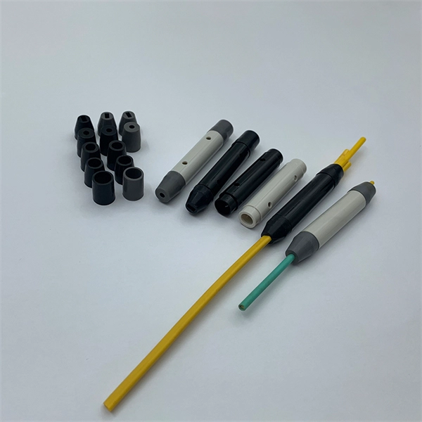
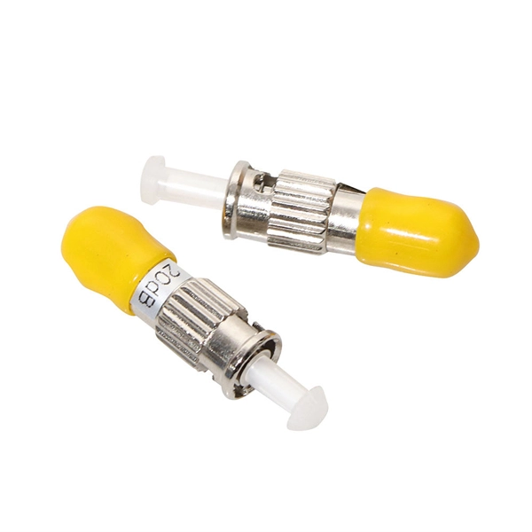
Engineered with tight mechanical tolerances and high reproducibility, the F‑SMA ensures consistent insertion loss (~0. 8 dB) and return loss (~12 dB), suitable for both standard and power-intensive applications. The SMA-905 Connector, also know as FSMA Connector, was one of the first fiber optic interconnect system that gained industry wide acceptance. Today the connector is still widely used for military, industrial, and medical applications. Our SMA-905 Connectors have a threaded coupling nut and feature. The SMA connector family utilizes a threaded coupling nut system for mating and de-mating. Available with zirconia or stainless steel ferrules with custom hole sizes, the SMA is an excellent choice for a robust, low-cost and reliable system. Features: Reliable, robust and time-tested as one of the. Note: In fiber optics, a single connector has no loss. The "loss of a connector" is defined as a "connection loss" caused by a mated pair of connectors. The lab method used to establish the average loss value of a connector design is shown below. For free-space optics, the F‑SMA Interface Module (IMOD) adapter provides precise. Return loss and VSWR (Voltage Standing Wave Ratio) are measurements for the same parameters; they have a logarithmic transition; see this link for a comparison table of return loss and VSWR. Its high-precision, ceramic ferrule allows its use with both multimode and single-mode fibers. The bayonet style, keyed.
[PDF]
For singlemode fiber, the loss is about 0. 5 dB per km for 1310 nm sources, 0. 5 dB/km at either wavelength for outside plant max per EIA/TIA 568)This roughly translates into a loss of 0. 1. To be able to judge whether a fiber optic cable plant is good, one does a insertion loss test with a light source and power meter and compares that to an estimate of what is a reasonable loss for that cable plant. The estimate, called a "loss budget" is calculated using typical component losses for. Manufacturers provide a fiber loss factor in dB per kilometer. Total fiber loss is calculated by multiplying the distance by the loss factor, considering the actual cable length. 25 dB/km (@1550nm) and 0. Understanding where those losses come from, and how to calculate them, is essential for designing a link that actually works. The decibel is. A loss budget in fibre optics is a detailed accounting of every potential source of signal attenuation (loss) in a fibre optic link. By accurately calculating and managing loss budgets, engineers and technicians can guarantee that optical signals reach their destination with enough power to be. After measuring the loss of a fiber link, you now have to determine if that fiber link loss is acceptable or not. Here are the details and instructions about each field and how they contribute to the calculation: 1. Attenuation Coefficient (dB/km): This value represents the inherent signal loss per kilometer of.
[PDF]
For singlemode fiber, the loss is about 0. 5 dB per km for 1310 nm sources, 0. 5 dB/km at either wavelength for outside plant max per EIA/TIA 568)This roughly translates into a loss of 0. 1 dB per. ity check. The fiber optic link attenuation is tested using an optical loss test set (OLTS) or a light source and power meter (LSPM) Figure 1). This type of testing is the most accurate testing available and is the most accurate characterization of the fiber optic system's apability. The estimate, called a "loss budget" is calculated using typical component losses for. Many solutions for 100 Gbit/s Ethernet have proposed to use CWDM to carry the multiple lanes over separate wavelengths on a single fibre. The presentation from Monterey anslow_01_0107. wavelength to justify the choice of CWDM channels to be analysed. It was. This document outlines the specifications for a single-mode optical fiber and cable designed for use around the 1310 nm zero-dispersion wavelength, suitable for both the 1310 nm and 1550 nm regions, and compatible with analogue and digital transmission. The acceptable dB loss for single mode fiber can vary depending on several factors. Measured in decibels (dB), insertion loss is the reduction in signal power that happens along any length of cable for any type of transmission. The longer the cable, the more a signal is reduced (or attenuated) by the time it reaches the far end. In addition to length, events that cause reflections.
[PDF]
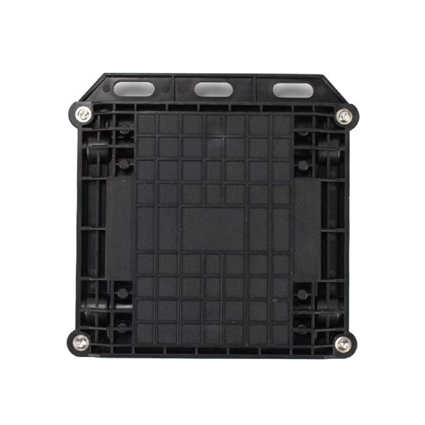
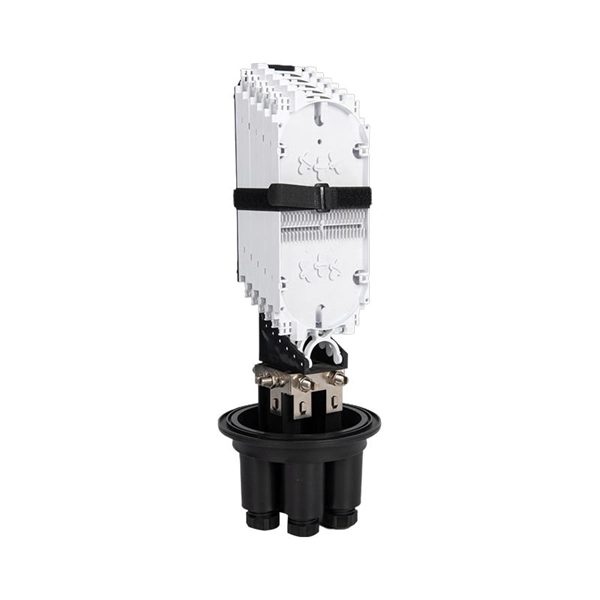
A splice box (also known as splice distributor) is a housing in which fiber optic cables begin or end. Fiber optics are fanned out in splice boxes that are situated at the end of fiber optic transmission paths. It typically consists of two parts: an outer housing and an internal structure. The main components of a splice box are the splice cassette that picks up the fibers and. The fiber optic dome splice closure is well-suited for splicing, distributing variable optical cables, and splitting. The solid box shell and the main structure are built to withstand harsh environments. The dome closure also protects fiber optic cables from vibration, impact, stretching, twisting. Home » Professional Insights » Fiber Optic Splice Closure: A Complete Guide to Types, Structure, Applications, and Selection In real fiber optic networks, cables are rarely installed as one continuous, uninterrupted length. Along transmission routes—whether in access networks, metro networks, or. Big space for managing pigtails or splitters. The 12 Port Fiber Distribution Box can connect up to 2 optical cables, providing space for distributors and 12 fuses. It is equipped with 12 SC adapters and can work in outdoor environments. Data communication networks. Horizontal fiber optic splice closures, also known as optical cable splice boxes, play an important role in the communications industry. It is a must-have device in the construction of optical cable line projects.
[PDF]
The medium sized closure shall accommodate up to 288 single fiber splices or 432 ribbon fiber splices. Buffer tubes shall not be subjected to a bend radius smaller. For protection against the outside plant environment and damage, splices require placement in a protective enclosure, usually called a splice closure. Splices are generally placed in a splice tray which is then placed inside a splice closure or integrated into a fiber pedestal for OSP. 2. Although a compact size, there is ample room to express 144 fiber cable. The FSDC series closures are fully sealed units which can be mounted on a. Fiber Splice Tray in Fiber Optic Splice Closure The fiber optic splice closure is component which is widely used in today's fiber optic network for outdoor applications and harsh environment. Fiber splice closures are not used occasionally — they are deployed extensively across every fiber network. The exact quantity depends on population density, network topology, and regional infrastructure planning. Below is a simplified example based on a 10 km coverage area serving approximately. Amphenol fiber optic sealed drop closures provide a versatile and functional cost-effective solution for FTTH network connections to the subscriber.
[PDF]
They shield 72 fragile optical fibers from harsh elements. Internal trays organize 4 cable ends for safe routing. Each closure offers 99. 9% protection against water. Additionally, the enclosure is crush-resistant, designed for 16 splice holders. They withstand temperatures of 176. Fiber optic splicing is a foundational process that directly dictates the performance and reliability of data transmission. The goal is to create a connection so precise that it minimizes signal loss and reflection. Two primary methods exist:. This guide is written to provide a complete and engineering-oriented understanding of fiber optic splice closures—from basic concepts and. A splice box (also known as splice distributor) is a housing in which fiber optic cables begin or end. The main components of a splice box are the splice cassette that picks up the fibers and. All product-related documents, such as certificates, declarations of conformity, etc., which were issued prior to the conversion under the name Pepperl+Fuchs GmbH or Pepperl+Fuchs AG, also apply to Pepperl+Fuchs SE. The fiber optic dome splice closure is well-suited for splicing, distributing variable optical cables, and splitting. The solid box shell and the main structure are built to withstand harsh environments. The dome closure also protects fiber optic cables from vibration, impact, stretching, twisting.
[PDF]
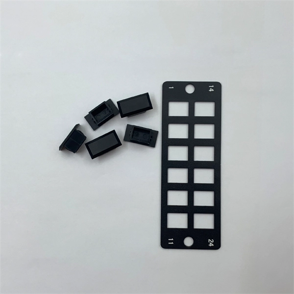
Join our mailing list and receive free updates every month! 24 Core IP68 Splice Enclosure with 2 x 12 Way Splice Trays (185 x 260 x 70) 2 ports in 2 ports out If you require a bespoke product please click here to contact us with your requirements for a quote. CD-24F-FS-W 24 Fibers Splice Tray provides secure organization and protection for up to 24 fusion splices, ensuring reliable performance in FTTx, data center, and enterprise networks. Its compact capacity and stackable design make it ideal for small-scale or distributed fiber management. These fiber splice trays, adapter panels and cable fan-out kits can accept up to 24 fibers. Made by AFL, Corning, Leviton, Pandit and other manufacturers. RLH Industries Outside Plant Fiber Splice Closure provides reliable and flexible installation for outdoor applications. The compact size and high quality construction allow for installation in both underground and aerial environments. The case lid is hinged for correct alignment and is secured with. Check each product page for other buying options. Price and other details may vary based on product size and color. Need help?. ZIP code to view pricing. ZIP code to. Whether you need fusion splicing for permanent, ultra-low-loss connections or mechanical splicing for rapid field deployment, our certified technicians deliver factory-quality results on every job — from hyperscale data centers and carrier-grade telecom networks to enterprise campus infrastructure.
[PDF]
The cost to install fiber optic cable ranges from $1. 50 to $42 per foot, with installation costs accounting for 60-80% of total project expenses. According to the Fiber Broadband Association's 2025 report, median costs are $8 per foot for aerial builds and $18 per foot for. Fiber optic cable installation costs between $1,500 and $7,000 for your home, with prices varying by cable length and installation method. The installation type you choose and the layout of your property determine the total labor and materials needed for your project. You should account for permit. Buying fiber optic installation services involves several cost components, with total price influenced by length, location, and access. This guide presents typical price ranges in USD to. Understanding the costs of fiber optic cable is a top concern for businesses planning network infrastructure upgrades. Whether you're expanding your data center, connecting multiple buildings, or future-proofing your connectivity, accurate pricing information helps you budget effectively. This guide breaks down everything you need to know before starting your fiber installation project.
[PDF]
The fiber optic distribution box accomodates up to 6 core fibers and supports outdoor applications within FTTH network system. The type of installation for 6 core distribution box is wall-mounted. The entry size of the drop cable is perfectly designed to accommodate 2x3 millimeters. Serves as a critical termination and distribution point in FTTH networks, offering mechanical protection for fiber optic connections. Ideal for both indoor (residential buildings, offices) and outdoor (exterior walls, utility areas) environments, ensuring durability in diverse conditions. The enclosure supports fiber splicing, splitting, and distribution within a single compact unit, ensuring organized cable routing and secure fiber. [Flexible Flip Board Design] The rotatable flip board allows for up to 180 degrees of flipping, enabling easy angle adjustments during use. [Robust Material] Constructed with abs material, this fiber distribution box offers excellent toughness, strength, wear, and impact. [Minimal Optical Loss]. FBR-11606 Fiber-Optic Distribution Box, 6-Core is a high quality product by Bud Industries used for electronic enclosure applications. It's easy to splice, split and manage the fiber in the box. FDB can provide solid protection and easy maintenance for FTTx network construction.
[PDF]
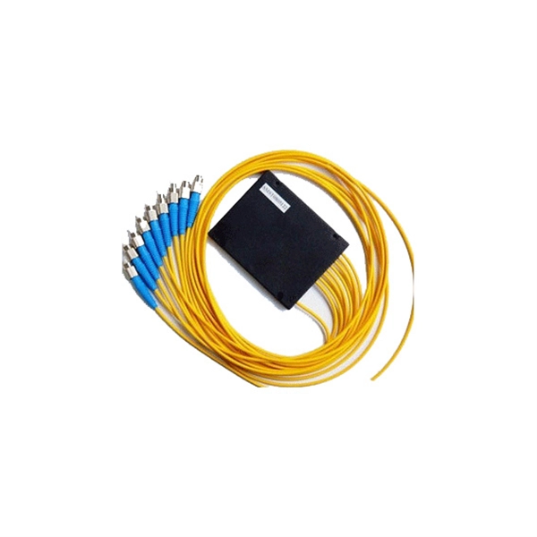
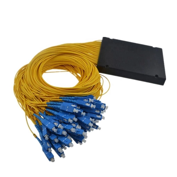
Optical splitters enable a signal on an optical fiber to be distributed among two or more fibers. Since fiber splitters contain no electronics nor require power, they are an integral component and widely used in most fiber-optic networks. A fiber optic splitter is a passive optical component that divides a single incoming optical signal into two or more outgoing signals, or combines multiple incoming signals into one. Unlike active devices (which require power), splitters operate without electricity, relying solely on the physics of. Optical cables, also known as fiber optic cables, consist of thin strands of glass or plastic fibers surrounded by a protective casing. These fibers transmit data as light signals, which are converted into electrical signals at the receiving end. The benefits of optical cables are numerous. A fiber-optic splitter, also known as a beam splitter, is based on a quartz substrate of an integrated waveguide optical power distribution device, similar to a coaxial cable transmission system. Its primary role is in Passive Optical Networks (PON), which are the foundation of. A fiber broadband provider typically determines and overall split ratio for the network, such as 1x32 or 1x64, and uses combinations of splitters to meet that ratio with each PON port. 1x32 splits were common in North America for G-PON architectures. As XGS-PON continues to be adopted, some service.
[PDF]
This step-by-step guide aims to provide a comprehensive understanding of the techniques and considerations involved in successfully connecting optical fibers, offering invaluable insights for professionals and enthusiasts in the field. In high-speed data networks, the seamless integration of fiber optic cables with SFP (Small Form-Factor Pluggable) modules is critical for reliable signal transmission. SFP transceivers bridge electrical and optical signals, making them indispensable in data centers, telecom networks, and. Proper connection of fiber optic cables is essential to harness these benefits fully, as even minor errors can lead to significant performance issues like signal loss. This article will guide you through the necessary tools, materials, and methods on how to connect fiber optic cables effectively. This section describes how to install optical transceivers on the SFP or SFP+ ports and connect them to the ports of the peer device using optical fibers according to the network plan. The USG supports both 1 Gbit/s, 10 Gbit/s, and 40 Gbit/s optical modules. The optical modules at both ends are. There are many types of fiber optic connectors, including SC, LC, FC, ST, D4, MU, MT/MPO, etc. These connectors can be divided into single-mode and multi-mode fiber optic connectors according to their structure and purpose. In this tutorial.
[PDF]
This guide will equip you with a systematic approach to diagnosing and resolving the most common optical link performance issues. By understanding the root causes, you can minimize downtime and ensure your network operates at its peak efficiency. When issues like signal loss, slow speeds, or intermittent connectivity arise, systematic troubleshooting is key. Why Do Fiber Networks Fail? Despite their robustness, fiber networks can fail due to:. This document describes how to troubleshoot fiber optic interfaces by addressing some of the fiber optic module and cabling specifications. There are no specific requirements for this document. The information in this document is based on all Catalyst 9000 Series switches. This includes Doppler. Fiber optic troubleshooting is an essential skill for network administrators, technicians, and engineers responsible for maintaining and repairing fiber optic systems. I switched to ATT fiber from Xfinity because usually fiber optic is faster. However I've had fiber optic for 2 days, and my gateway is constantly disconnecting from the network. I know the technician said something about. Optical fiber networks are essential for delivering high-speed internet and reliable communication. Despite their advanced technology, these networks can encounter problems that impact performance. Effective troubleshooting is crucial to maintaining a smooth and efficient network. This blog post.
[PDF]
With a variety of kit options available, you can choose between the easy-to-use Quick Clean™ Cleaners, the convenient cleaning cube/card, and the best optic solvent pen to clean both patch cords and fiber.
[PDF]
Interactive anomalies of pipelines represent important contributors to pipeline incidents, but monitoring interactive anomalies is challenging. This paper presents an approach to monitor interactive bend.
[PDF]
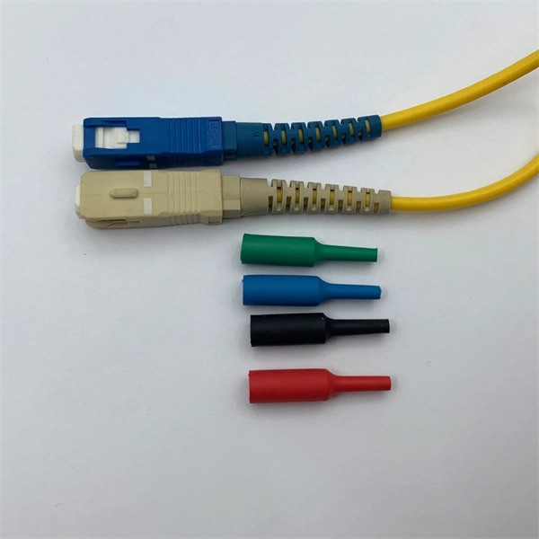
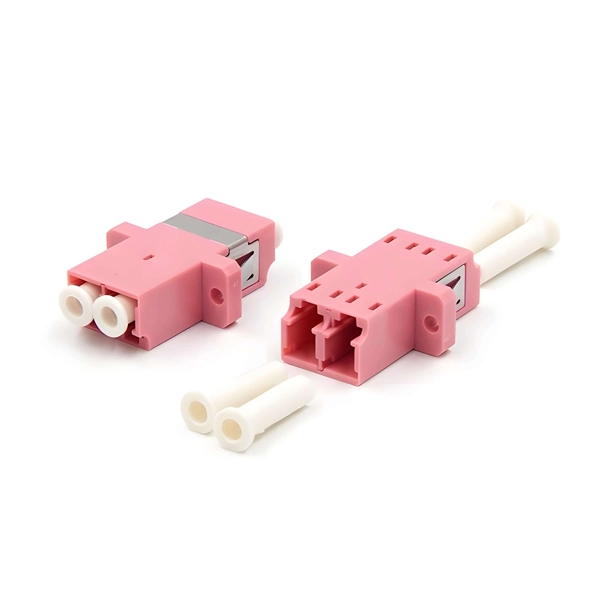
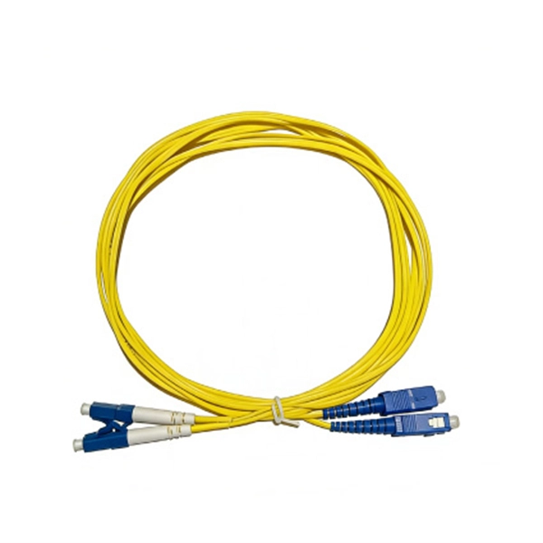
A variety of optical fiber connectors are available, but SC and LC connectors are the most common types of connectors on the market. Typical connectors are rated for 500–1,000 mating cycles. The main differences among types of connectors are dimensions and. An optical fiber connector is a device used to link optical fibers, facilitating the efficient transmission of light signals. They come in various types like SC, LC, ST, and MTP, each designed for specific. Fiber connector types LC, SC, FC, ST, MTP, and MPO are widely used in past and present. What are the differences between them? Who is the most popular one? Find the answer in the article. What is a Fiber Connector? The optical fiber connector is a kind of detachable passive optical component used. Fiber optic cable assembly quality hinges on selecting the right connector type—most commonly LC, SC, or ST—to match device ports and installation environment. When selecting the appropriate optical module for a network application, one crucial factor to consider is the type of fiber connector it employs. Fiber optic connectors are used to the mechanical and optical means for cross connecting fibers. There have been many types of connectors developed for fiber cable. With the demands of different application scenarios.
[PDF]