We experimentally demonstrate 100 Gb/s bidirectional transmission over 40 km using a multi-wavelength bidirectional optical sub-assembly (BOSA) based on a single bidirectional multi-wavelength Mux/Demux. The Mux/Demux consists of an optical zig-zag glass block and thin film. A bidirectional SFP (BiDi SFP) provides an efficient solution by enabling data transmission and reception over a single strand of optical fiber. This physical-layer design instantly doubles existing cable plant capacity without requiring expensive new. BiDi optical modules can do this by utilizing full-duplex communication over a single fiber strand via two wavelengths. By reading this blog, you will understand how SFP BiDi technology allows you to save fiber, reduce costs, and simplify installation while enabling your network to increase. In the world of transceivers, BiDi stands for Bi-Directional. In terms of SFPs, BiDi transceivers transmit at one wavelength and receive at another. BiDi SFPs connect to a fiber cable using only one. A 1G BiDi transceiver solves these challenges through single-fiber bidirectional transmission, giving networks a more economical and efficient upgrade path.
[PDF]
To help you achieve stable and reliable 800G connections between different brands and models of equipment, we have prepared this concise selection guide. As network speeds escalate to 400G and 800G, proper cabling infrastructure becomes critical for maintaining signal integrity and maximizing performance. Extreme Networks cables provide optimized solutions for high-speed data centers, offering reliable connectivity for next-generation applications. A reliable sourcing strategy must prioritize Multi-Source Agreement (MSA) compliance, rigorous EEPROM compatibility. 800G Ethernet DAC cables, as a direct-connection solution based on high-speed copper cabling, are widely used in short-distance connection scenarios within racks and between adjacent racks. With their simple structure, low power consumption, and convenient deployment, DACs provide a cost-effective. This article provides a comprehensive overview of FS's 800G transceivers and DAC/AOC cables, including product lists, advantages, and application scenarios, offering tailored network solutions for data centers. FS provides a comprehensive portfolio of 800G optical transceivers and DAC/AOC cables. At 400G, interconnect selection was a two-step process: measure the distance, pick copper or fiber. Passive copper comfortably reached 3–5 meters. Multimode fiber handled everything from the rack to the end of the row. 800G changed the underlying physics.
[PDF]
Two major factors should be considered: (1) the number of bits required to produce a statistically meaningful BER/BLER result, and (2) the baseband functionality required to verify coded BER/BLER. Bit Error Rate (BER) testing is a crucial aspect of evaluating the performance of digital communication systems. It involves measuring the rate at which errors occur in a transmitted bitstream compared to the expected bitstream at the receiver end. The BER measurement helps in assessing the quality. In digital transmission, the number of bit errors is the number of received bits of a data stream over a communication channel that have been altered due to noise, interference, distortion or bit synchronization errors. Adhering to strong layout practices ensures that the bit error rate is a random process rather than an indicator of design issues. The Bit Error Rate Analysis app is designed for analyzing BERs.
[PDF]
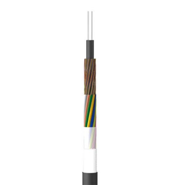
This comprehensive guide provides step-by-step instructions for sizing electrical cables in accordance with Australian Standard AS/NZS 3008. Electrolytic Tough Pitch (ETP) : The workhorse for most applications - 99. 9% pure with oxygen molecules peppered throughout the structure. Offers optimal balance of conductivity and cost Oxygen-Free Copper (OFC) : Created in oxygen-free environments, eliminating oxide impurities. Has marginally. Selecting the correct cable size is not just about electrical efficiency—it is a critical safety requirement. Under-sized cables lead to insulation failure, fire hazards, and significant equipment damage. Whether you're an electrical engineer, contractor, or student, this resource will help you master the essential calculations for selecting the. The National Electrical Code (NEC) provides clear guidelines for ground wire sizing through Table 250. 122, but understanding how to apply these requirements correctly can make the difference between a safe installation and a costly code violation. Proper grounding conductor sizing is critical for. Professional electrical wire sizing tool based on National Electrical Code (NEC) standards. Calculate proper wire gauge, voltage drop, and ampacity for safe electrical installations. Input your electrical parameters to get accurate wire size.
[PDF]
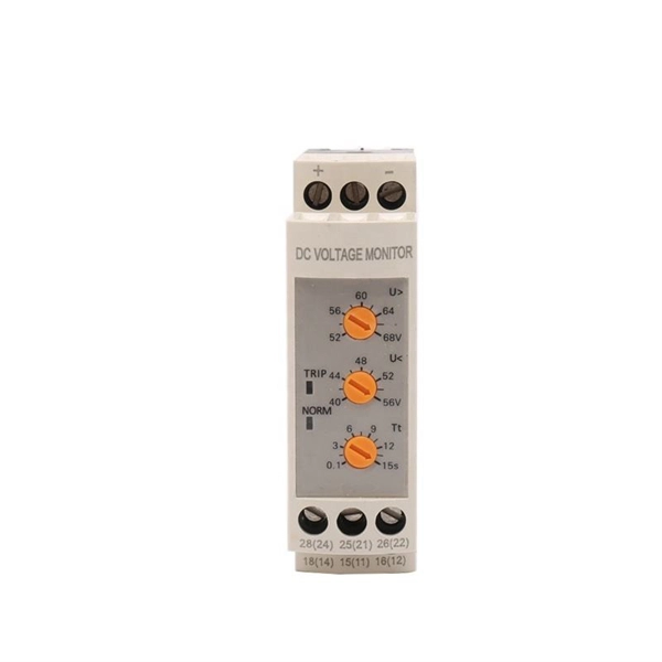
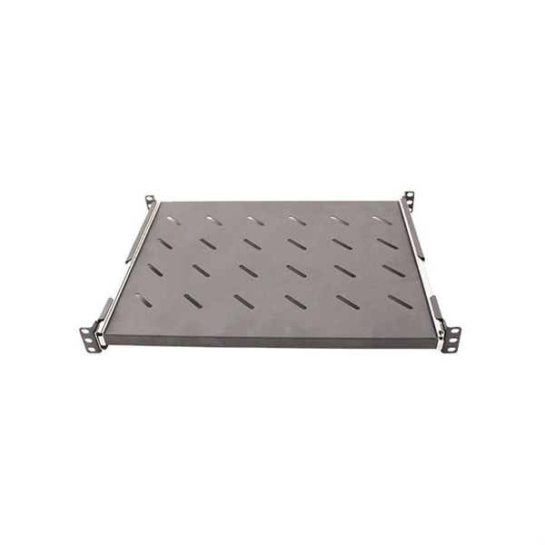
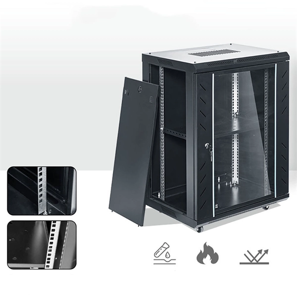
Standardized Dimensions: The rails have standardized dimensions, allowing easy integration of various modular equipment. The most commonly used rails are 35 mm wide, although other width options may also be available. Ease of Installation: DIN rails are designed for easy. At its core, a DIN rail is a standardized metal rail that provides a mounting system for all sorts of electrical and industrial control gear you'd find inside equipment racks, enclosures, and control panels. These rails, usually made from steel or aluminum, let you securely snap components like. This guide will provide you with the necessary information regarding the development of din rail and its standards, benefits, types, selection, and installation, including their specifications. What Are DIN Rails? 2. Lianjie - Blog - Electrical Equipment - What Is a DIN Rail? Mounting Guide for Electrical Panels 2026 What Is a DIN. DIN rails are standardized mounting rails designed for modular electrical equipment such as relays, automation devices, switches, circuit breakers, and other components to be mounted in electrical distribution boards. These products are typically made from cold rolled carbon steel sheet with a zinc-plated or chromated bright surface finish. Defined by standards such as IEC 60715 and EN 50022, the most common type is the 35mm “Top Hat” rail (TS35). It allows for the rapid, snap-on installation of modular.
[PDF]
This application note explains how Site Master is used to measure cable insertion loss with different test methods and how to predict the maximum allowable cable insertion loss through manual calculations. Desktop Insertion Return Loss Tester with color screen has stable and reliable performance, which integrates stable light source, high-precision power meter, insertion loss meter and return loss meter into one multifunction instrument. Based on domestic customers'. Modern handheld analyzers, like the Keysight FieldFox Analysers, are designed specifically for cable and antenna testing (CAT), offering fast and accurate insertion loss testing across a wide frequency range. These tools are invaluable for both installation and maintenance, enabling field. Insertion loss is expressed in decibels or dB. The decibel is a logarithmic expression of the ratio of output voltage (voltage of the signal received at the end of the link) divided by input voltage (the voltage launched into the cable by the transmitter). 0 PCB transmission line losses in a PCB production environment. In wireless communication systems, the transmit and receive antennas are connected to the.
[PDF]
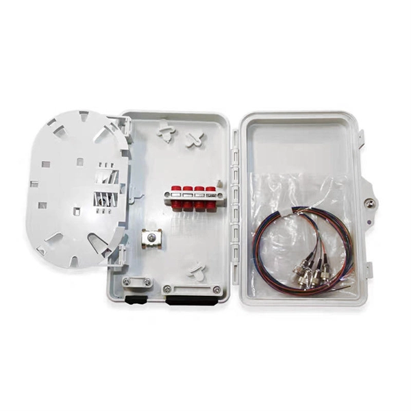
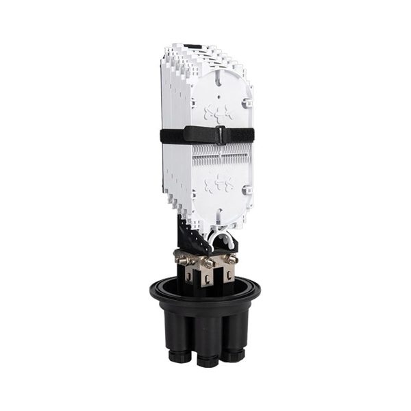
Gray; Suitable for 1 piece of 1 × 16 (or two pieces of 1 × 8) blockless type PLC splitters; With the adaptor panel for max. 16 pieces of SC or duplex LC (SC type); Adaptors and PLC splitter NOT included; 1 midspan port and 16 drop cable ports; Dimensions (mm): 306 (L) ×253 (W)×92 (H); Wall mounting. Check each product page for other buying options. Need help?. How can we improve? Choose from our selection of junction boxes, including over 2,800 products in a wide range of styles and sizes. Same and Next Day Delivery. © 2024 E-Talk Maldives. Underground vaults or enclosures are used in all fiber optic networks that use GPON networks for FTTH or Fiber To The Home Deployments that are private or federal funded. Orders. What Is a Fiber Distribution Box (FDB)? A fiber distribution box (FDB) is a passive enclosure that provides secure splicing, termination, and distribution of optical fibers. It typically contains splice trays, adapters, and cable routing components to manage fiber connections. FDBs are used to.
[PDF]