This research report provides a comprehensive analysis of the Passive Optical Components market, focusing on the current trends, market dynamics, and future prospects. How does 6W market outlook report help businesses in making decisions? 6W monitors the market across 60+ countries Globally, publishing an annual market outlook report that analyses trends, key drivers, Size, Volume, Revenue, opportunities, and market segments. 22 USD Billion in 2024. The Passive Optical Component industry is projected to grow from 17. 01 USD Billion by 2035, exhibiting a compound annual growth rate (CAGR) of 6. 8% during the forecast period. Passive Optical Components are critical elements in fiber optic. Global passive optical component market is estimated to be valued at US$ 86. 2% from 2026 to 2033. Discover market dynamics shaping the industry: Download Free Sample Global passive. The Global Passive Optical Components Market was valued at USD 38. These components play a crucial role in the transmission of data, voice, and video signals over optical networks. The market for passive optical.
[PDF]
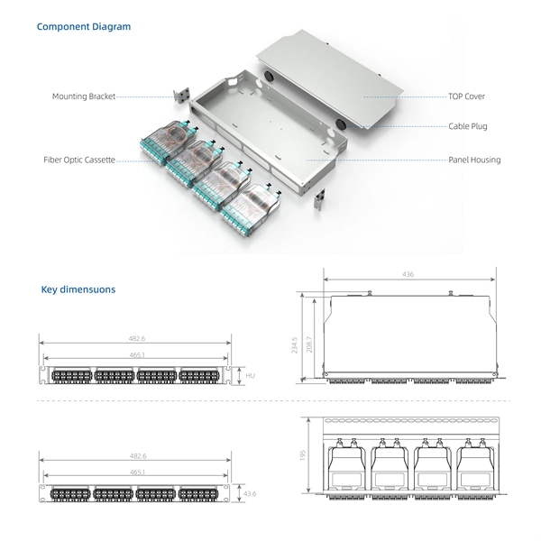
pigtails can be divided into single-mode (colored yellow) and multimode (colored orange) fiber. Multimode pigtails use 62.5/125 micron or 50/125 micron bulk multimode fiber cables and terminated them with multimode fiber optic c. pigtails can be divided into single-mode (colored yellow) and multimode (colored orange) fiber. Multimode pigtails use 62.5/125 micron or 50/125 micron bulk multimode fiber cables and terminated them with multimode fiber optic connectors at one end. 10G multimode fiber cables (OM3 or OM4) are also available in optic pigtails. The jacket color of 10. Fiber Optic Pigtails, In fiber optic cable installation, how cables are attached to the system is vital to the success of network. If done properly, optical signals would pass through the link with low attenuation and little return loss. pigtail offers an optimal way to joint optical fiber, which is used in 99% of single-mode applications. This pos. According to different types of pigtail cable connector terminated at the end, there are LC fiber pigtail, SC pigtail, ST pigtail, FC pigtail, fiber pigtail and so on. With different structures and appearance, each of them has their own advantages in different applications and systems. Let's go through some widely used ones. SC Pigtail: SC pigtail.
[PDF]
At the heart of every optical transceiver lie three essential components, often called the “Three Pillars” of optical communication: Laser — generates light. Modulator — encodes data onto the light. Photodiode — decodes light signals back into electrical form. As an essential component of optical fiber communication, optical modules are optoelectronic devices that facilitate the conversion between optical and electrical signals during the transmission process. Operating at the physical layer of the OSI model, optical modules are core devices in optical. An optical module usually consists of an optical transmitting device (TOSA, including a laser), an optical receiving device (ROSA, including a photodetector), functional circuits,main control circuit board (PCBA), housing and optical (electrical) interface and other components. Together, lasers, modulators, and. That is, metal medium communication represented by coaxial cables and network cables is gradually being replaced by optical fiber media. Composition of Optical Modules The optical module, known as Optical Transceiver in. This comprehensive guide breaks down the internal structure, core components (TOSA, ROSA, lasers), and operational mechanisms of SFP optical modules, enriched with technical insights and real-world applications. These modules typically consist of a transmitter, which converts electrical signals into a light signal, and a receiver, which converts the received signal back.
[PDF]
As illustrated in typical SFP internal structure diagrams, the module's core components include an optical transmitter assembly (TOSA), laser driver, optical receiver assembly (ROSA)—some high-sensitivity modules (like L16. 2) use APD receivers, which require an additional booster. As a key element in optical communication systems, optical transceivers serve as media between network devices to transmit and receive data. There has been lots of articles and guides on transceiver modules in the perspective of the package type while only a few of them cover the internal elements. Optical modules are devices used to connect network devices, transmit and receive data between network devices, and can be used to convert optical and electrical signals. The optical module is a very important component in an optical communication system. When you remove the metal housing of the optical transceiver, you will find that the internal components are connected to each other. The following section will focus on. In the era of 5G, AI, and high-speed data centers, optical modules serve as the core bridge for converting electrical signals to optical signals (and vice versa), enabling fast, reliable data transmission across networks. Among various optical module form factors, SFP (Small Form-Factor Pluggable). The optical transceiver module is mainly composed of three parts: housing, optical device and integrated circuit board. The following section will focus on.
[PDF]
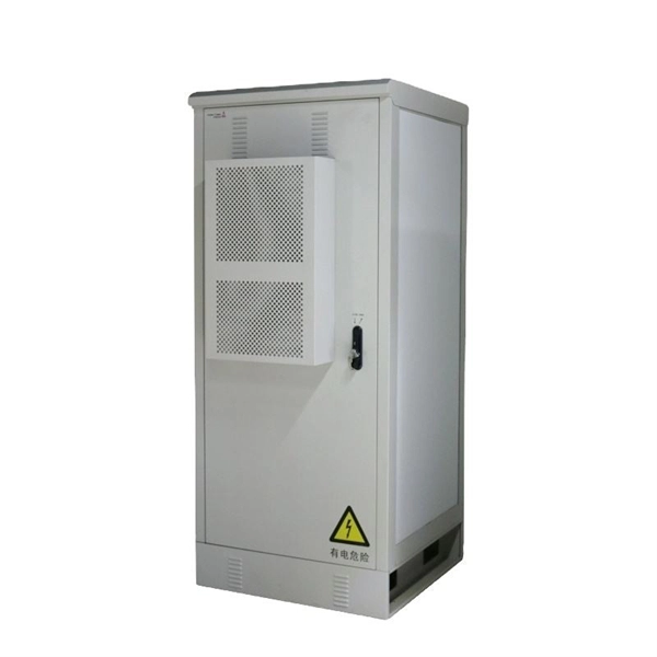
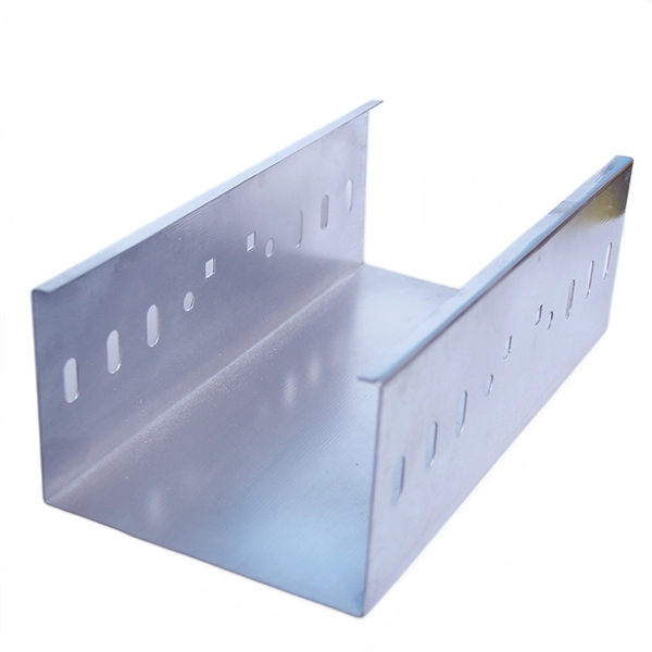
Cable tray grounding wire is the safety connection that links your electrical system's cable tray to the ground. This provides a safe path for any stray electrical currents to flow safely into the earth, avoiding damage to your equipment and reducing the risk of electric shocks. There is no restriction as to where the cable tray system is installed. The metal in cable trays may be used as the EGC as per the limitations. Cable tray may be used as the Equipment Grounding Conductor (EGC) in any installation where qualified persons will service the installed cable tray system. Consider it as an emergency electricity exit. The main purpose of. Grounding in cable trays is an important practice to increase electrical safety and prevent hazards in case of faults. The methods and materials used may vary depending on the structure of the installation. However, the main principle should always be to ensure safe and effective grounding. It involves connecting cable trays to the facility's grounding system, providing a low-impedance path for fault currents and protecting personnel.
[PDF]
On the US market, a 5. 26 mm 2 (10 AWG) ground wire must be used, and in all other markets a 6 mm 2 must be used. Grounding of the units: Attach a ground wire from one of the threaded studs (A) at the bottom of the housing, to the mounting plate (B). Power from factory ground must be installed by a qualified electrician. Each DISTRIBUTION BOX and controller must be grounded. In the low-voltage three-phase four-wire neutral point directly grounded line, the construction unit should. Repeated grounding can be grounded directly from the neutral line or from the housing of the zeroing device. It looks like two lines, and in fact they are all together. The main functions of repeated grounding are as follows; (1) Reducing the ground voltage of the leakage device housing. In the. Today, we're diving deep into the world of distribution box grounding, breaking down the standards, and shining a light on those sneaky mistakes that even experienced electricians sometimes make. Good equipment grounding ensures personnel safety. Most North American distribution systems have a neutral that acts as a return conductor and as an equipment. This paper is intended to address how grounding system effectiveness affects each of these goals. Key Words - Grounding, Earthing, Safety, Surge Protec-tion, NESC, Neutral-to-Earth Voltage, Ground Currents, Stray Voltage. This paper is intended to give an overview of the vari-ous relationships.
[PDF]