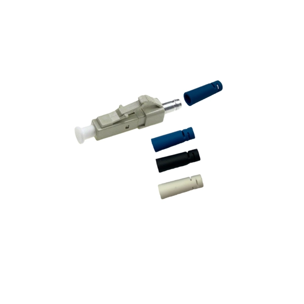
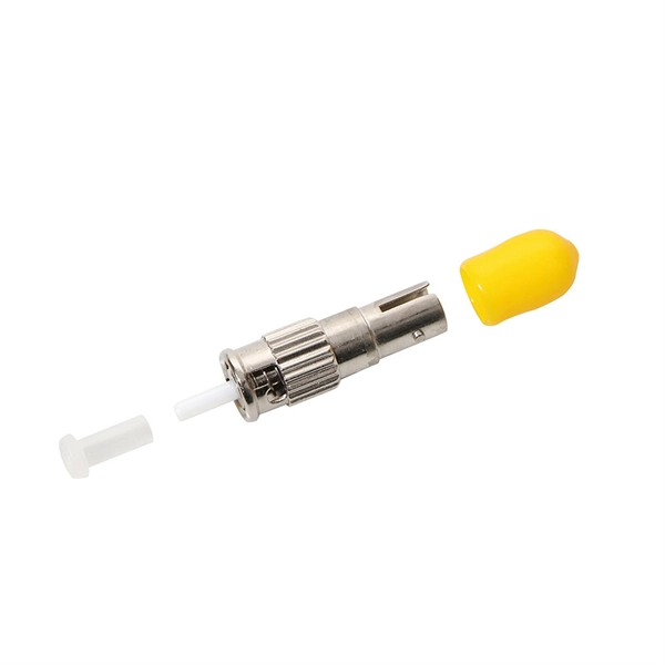
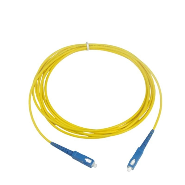
Mouser offers inventory, pricing, & datasheets for Duplex Fiber Optic Connectors. Check each product page for other buying options. QIANRENON LC Fiber Panel Mount Adapter LC Fiber Optic Connector Socket LC Fiber Coupler Module. XLR Panel/D-Panel Mount, for Fibre Optic Network LAN Integrated Cabling Need help?. Pricing (USD) Filter the results in the table by unit price based on your quantity. A tariff of 10% may be applied if shipping to the United States. A. Fiber Optic Connectors are the ends used to terminate optical fiber cable. The connector styles are DNP, ESCON, FC, FDDI, FSD, FSMA, LC, MPO, MT-RJ, MU, SC, SCRJ, SCRJ and Power Jack, SMA, ST, TNC, and VF-45. The mode options are multimode (OM1, OM2, OM3, OM4), POF, and Singlemode (OM1). These. High quality faceplates, RJ45 plugs, and copper, audio, video, and fiber optic modules from Molex, Leviton, CommScope, SignaMax, and more. COM supplies different types of fiber optic wall plates outlets, including angled ports fiber optic wall plate outlets. The angled opening provides a low profile and strain relief and allow fiber connectors and jumpers. Corning wall-plate outlet (WLL) is a highly configurable outlet product, available in both single- and double-gang configurations. It is designed for use within fiber-to-the-desk (FTTD) applications but may also be used to connect telephones and other peripherals to a network. A variety of fiber and.
[PDF]
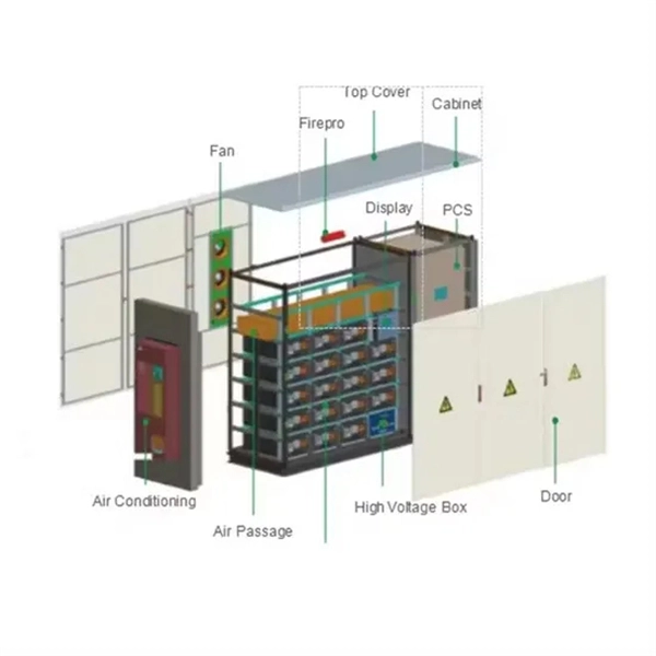
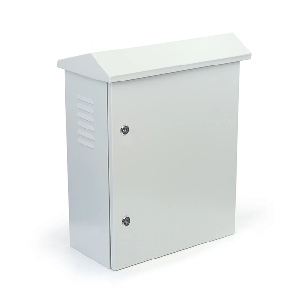
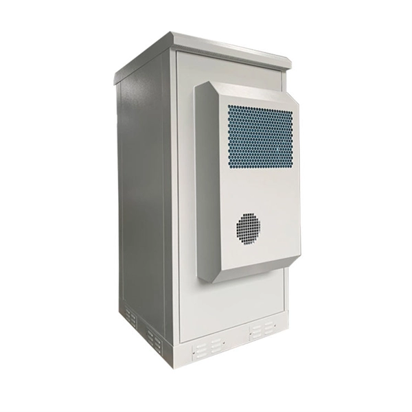
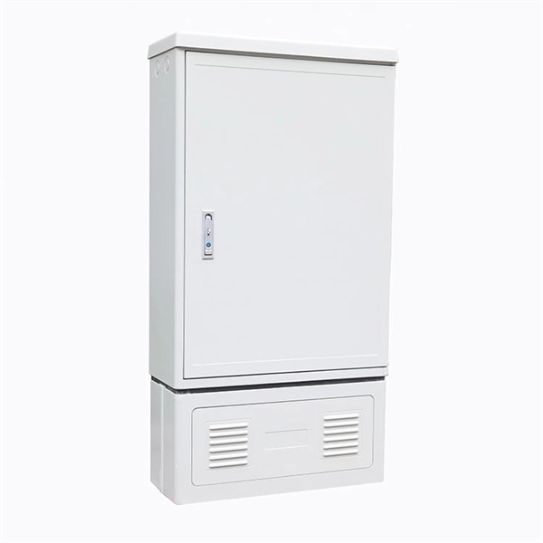
A distribution box, also known as a distribution panel or board, is a cabinet that holds electrical parts used to supply power to multiple circuits within a system. It acts as the central point where electricity distribution is managed inside a building. A distribution boxes is an essential device that manages the safe and efficient flow of electrical power throughout different areas of a building or facility. It is commonly used in homes, offices, and industrial settings to control and protect electrical circuits. Understanding its significance. The distribution panel, frequently called a breaker box or service panel, functions as the nerve center for a structure's entire electrical system. This metallic enclosure receives the incoming power supply from the utility company and organizes it for use throughout the building. From powering homes and industrial facilities to supporting medium-voltage infrastructure, these enclosures ensure safe, efficient, and reliable power distribution. Today, electrical systems are essential for homes and industries.
[PDF]
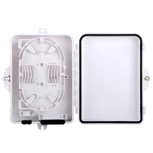
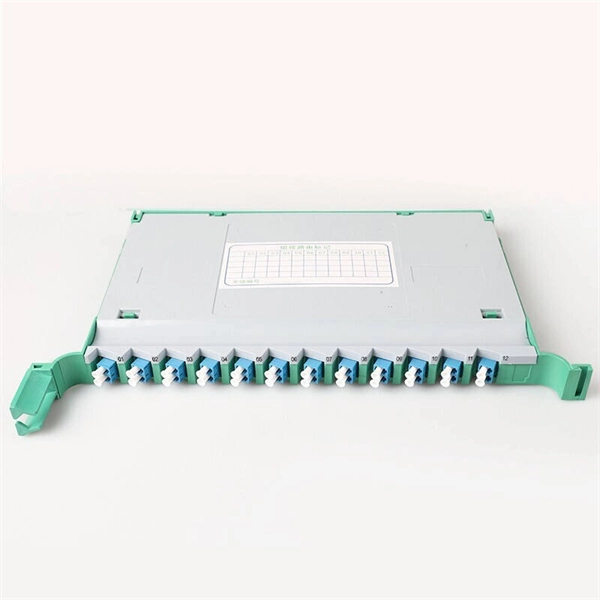
The panel can be pre-loaded completely with the required adapters or pre-loaded with pigtails and splice accessories. The tray is locked by 2 plastic latches and lowers to a 45 degree angle when fully extended. Installation and labeling are simple and easy. FS offers FHD® FAPs and FHU® 1U fibre patch panel with LC, SC, MTP®/MPO connectors in singlemode/multimode fibre to deploy medium for high-density fibre optic network applications. A patch panel or fibre distribution panel is a metal frame with pre- punched holes equally spaced horizontally along the front face. Unpopulated patch panels can be configured with bulkhead. A carefully selected range of fibre optic termination and patch panels from leading brands including Panduit, Canford and Speedway. A handy tool to for quickly finding a populated fibre connection panel that meets your requirements. Rack mounted fibre patch panels create a convenient, professional and easy access way to organise your fibre cables into a cabinet. Latest Optical Fibre Patch Panels for fibre installations.
[PDF]
Please view our full RLH price list and contact us at info@fiberopticlink. com if you have any questions or special project needs. A fiber optic distribution panel (also known as a fiber distribution frame or FDF) serves as a centralized hub for managing, terminating, and distributing fiber optic cables in telecommunications and data networking systems. Fiber Adapter Panels fit all Multilink rack and wall mount Fiber Distribution Units. Panels are available in Simplex or Duplex adapter format. Patch panels are integral components of any network system. This equipment helps keep data systems and server rooms organized, functional and easily. Fiber optic patch panels are designed either to support direct termination or fusion splicing of the optical fibers. Fiber optic patch panels allow the optical splices of the fiber. Belden offers clean, simple, and lightweight Wall-Mount Panels within its DCX, FiberExpress (FX) UHD and ECX ecosystems. The versatile DCX Zero-U wall-mounting devices hold DCX cassettes and adapter frames and can be mounted under standard cable basket trays. The FX UHD and ECX modular platform of. UnitekFiber offers a wide variety of wall mounted fiber optic enclosures, including indoor fiber optic enclosures, outdoor rated fiber optic enclosures, plastic fiber optic enclosures or metal fiber optic enclosures. The wall mount fiber enclosure, also known as a wall mount fiber patch panel, is a.
[PDF]
In this video, we take you through the step-by-step installation of Optical Distribution Frames (ODF) and Optical Fiber Patch Panels—key components in setting up a robust fiber optic network. At Eman Communications, we specialize in delivering high-quality installations that ensure opt. more In. Fiber optic patch panels are mostly mounted in 19 inch relay racks, but they can also be mounted on freestanding rails, in cabinets and also on walls. The fiber optical patch panel is convenient for people to easily access the optical fiber cable in the panel. Keeping this page as a placeholder for now. Have any questions? Talk with us directly using LiveChat. An ODF is a centralized platform designed for terminating, cross-connecting, and managing optical fibers. It ensures fiber management is structured, minimizes signal loss, and provides accessibility for maintenance and future expansion. ODF Rack/Cabinet: Physical frame housing all terminations and. To connect fiber optic cables to a patch panel, users must follow a specific procedure that ensures proper connectivity and signal transmission. Here is a step-by-step guide on how to connect fiber optic cables to a patch panel. Step 1: Gather the Tools and Equipment The first step in connecting.
[PDF]
On the US market, a 5. 26 mm 2 (10 AWG) ground wire must be used, and in all other markets a 6 mm 2 must be used. Grounding of the units: Attach a ground wire from one of the threaded studs (A) at the bottom of the housing, to the mounting plate (B). Power from factory ground must be installed by a qualified electrician. Each DISTRIBUTION BOX and controller must be grounded. In the low-voltage three-phase four-wire neutral point directly grounded line, the construction unit should. Repeated grounding can be grounded directly from the neutral line or from the housing of the zeroing device. It looks like two lines, and in fact they are all together. The main functions of repeated grounding are as follows; (1) Reducing the ground voltage of the leakage device housing. In the. Today, we're diving deep into the world of distribution box grounding, breaking down the standards, and shining a light on those sneaky mistakes that even experienced electricians sometimes make. Good equipment grounding ensures personnel safety. Most North American distribution systems have a neutral that acts as a return conductor and as an equipment. This paper is intended to address how grounding system effectiveness affects each of these goals. Key Words - Grounding, Earthing, Safety, Surge Protec-tion, NESC, Neutral-to-Earth Voltage, Ground Currents, Stray Voltage. This paper is intended to give an overview of the vari-ous relationships.
[PDF]
On the US market, a 5. 26 mm 2 (10 AWG) ground wire must be used, and in all other markets a 6 mm 2 must be used. Grounding of the units: Attach a ground wire from one of the threaded studs (A) at the bottom of the housing, to the mounting plate (B). Attach a second grounding wire from the mounting. The correct connection method of Distribution box grounding wire mainly includes the following steps: 1. Find the grounding bar or PE bar Open the distribution box and find the position marked with the grounding plate or PE letter. The basic rule achieves this through an equipment grounding jumper; four exceptions. An equipment grounding conductor passing through the box without a splice is not required to be joined inside the box to others that are spliced in the box. 148 addresses the continuity of equipment grounding conductors and their attachment in boxes. Not all boxes are metal or provide. Correct grounding of services depends upon understanding the definition and role of the grounded conductor. The neutral conductor is typically the grounded conductor connected to the system's neutral point, carrying current under normal operation. Whether you're a seasoned pro or just starting out, this comprehensive guide will give you practical.
[PDF]
The primary function of a feeder wire is to facilitate bulk power transfer from a central source to a subpanel or a secondary distribution center. An example is the large cable running from the main service panel to a subpanel in a detached garage, basement, or workshop. A main panel and a sub-panel are both important components of an electrical distribution system. It is usually located where the main electrical service enters the building, often on an. Main feeder wires are the arteries of a building's electrical system, designed to safely and efficiently transport a large volume of power from the service entrance to secondary distribution points. They form the backbone of the electrical distribution network, handling the substantial current. An electrical sub panel, also known as a sub distribution board or sub circuit breaker panel, is a smaller secondary panel connected to the main electrical panel in a building. It serves as an extension of the main electrical panel to distribute power to different areas or circuits within a. Distribution board is a safe system designed for house or building that included protective devices, isolator switches, circuit breaker and fuses to safely connect the cables and wires to the sub circuits and final sub circuits including their associated Live (Phase) Neutral and Earth conductors. The distribution box acts as the center of power distribution, distributing electricity to all connected devices.
[PDF]
Ungrounded: There is no intentional ground applied to the system-however it's grounded through natural capacitance. Reactance Grounded: Total system capacitance is cancelled by equal inductance. This decreases the current at the fault and limits voltage across the arc at the. In electrical engineering, a protective relay is a relay device designed to trip a circuit breaker when a fault is detected. : 4 The first protective relays were electromagnetic devices, relying on coils operating on moving parts to provide detection of abnormal operating conditions such as. To attain the desired reliability, the power system network is divided into two different protection zones. They are generator protection, transformer protection, bus protection, transmission line protection and feeder. Recognized under 2(f) and 12 (B) of UGC ACT 1956 (Affiliated to JNTUH, Hyderabad, Approved by AICTE - Accredited by NBA & NAAC – 'A' Grade - ISO 9001:2015 Certified) Maisammaguda, Dhulapally (Post Via. Kompally), Secunderabad – 500100, Telangana State, India To introduce all kinds of circuit. A protection relay is a crucial component of electrical systems that safeguard infrastructure, employees, and equipment from electric problems and malfunctions. It functions as a watchdog by constantly surveying multiple system components including voltage, current, frequency, and phase angle.
[PDF]
NEC (National Electrical Code) Article 800 covers the general requirements for communications systems, including wiring methods, grounding, fire resistance, and installation practices for cables and equipment. The term “cable” means stranded conductor or a combination of conductors that includes Fiber Optic Supply Cable, Fiber Optic Communication Cable, or Non–Dielectric Fiber Optic Cable as defined in Rule 20. The term “messenger” is defined in Rule 22. The. This Applications Engineering Note (AE Note) discusses conventional bonding and grounding practices for conductive fiber optic cable and hardware installations within the scope of the National Electrical Code (NEC). This AE Note does not address outside plant fiber optic installations or. ned herein and with other Sections of this Specification as applicable to the completion of the installation. It applies to circuits that extend from the communications utility (such as telephone or. Article 800”General Requirements for Communications Systems covers general requirements for installing communications circuits, community antenna television and radio distribution systems, network-powered broadband communications systems, and premises-powered broadband communications systems. to n utral comm.
[PDF]
7 meters) high makes it easily accessible without the need to bend or stretch excessively. This height also safeguards the box from potential water spills or accidental impacts. The proper installation of a distribution box involves placing it at the right height to ensure safety and convenience. This enclosure houses the circuit breakers, which are overcurrent protection devices designed to automatically shut off power during a fault or. However, the key to a safe and reliable system lies in proper installation. If it's done poorly, you risk short circuits, fire hazards, or system failure. Done right, it ensures safety, compliance, and long-lasting performance. In this guide, we'll break down everything you need to know to install. The International Standards of Practice for Inspecting Commercial Properties (ComSOP) states that the inspector should report on the lack of accessibility or working space for electrical panels and gear that would hamper their safe operation, maintenance, and inspection. Many jurisdictional and. Governed by NEC 110. 26, these rules define the minimum Spaces about electrical equipment necessary for workers to perform tasks like inspection, maintenance, and replacement safely. Note to paragraph (b): American National Standard National Electrical Safety Code, ANSI/IEEE C2-2012 contains.
[PDF]
In this step-by-step tutorial, we'll cover: ✅ Tools you need ✅ Safety precautions ✅ Mounting the box ✅ Wiring tips ✅ Final checks Perfect for beginners, DIYers, and electricians who want a clear installation guide. more Learn how to properly install an electrical. Electrical switch box wiring is a critical aspect of any electrical installation. The electrical panel box wiring diagram provides a visual representation of. A junction box provides a code-approved place to house wire connections, whether for outlets, switches, or splices. Here's how to install one. We may be compensated if you purchase through links on our website. It acts as a central connection point for various electrical wires, allowing for the easy distribution of electricity to different fixtures and devices. A properly installed and wired junction box ensures the safety and. Are you ready to master the skill of building electrical panels? This detailed guide provides an excellent base for beginners. Learn about the essential components of panels, such as the circuit breakers and fuses that safeguard against hazards. Then, delve into complex wiring configurations.
[PDF]
This guide will walk you through the essential steps to design and wire an efficient PLC control cabinet. We'll cover key topics like selecting components, cabinet layout, cooling, wiring, and safety to help you create a reliable and durable system. What is a PLC. Designing a plc cabinet takes more than just picking parts and wiring them up. You want every panel to meet strict safety requirements and deliver top efficiency for your automation projects. What is a PLC Control Cabinet? A PLC control cabinet plays a vital role in industrial automation by housing and. Electrical control panel wiring should be organized well or it can be unsafe or even hazardous. It is important that wiring be held together neatly using cable ties to ensure that everything is in an organized and neat order. It is advisable for everything to be tightly connected and there should. Construct control cabinets in a fraction of the time through simple manual wiring without tools: WAGO Push-in CAGE CLAMP ® Technology allows you to reduce costs, increase the safety of your application and reduce the time and effort for control cabinet wiring by up to 50 percent. With Smart. Before wiring, read the drawings carefully and understand the designer's intent. Do not rely solely on personal experience. If any discrepancy or ambiguity is found, confirm with the designer before starting work. Keep wiring order clear and verifiable. Wiring procedures should be simple and.
[PDF]
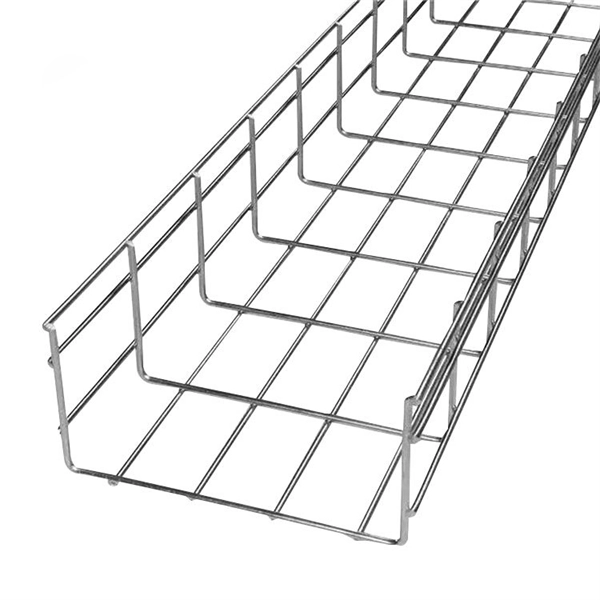
A T-tap wire connector, also known as a T-splice connector, is used to tap into existing wires and is characterized by its T-shaped design with three points of entry for wires. This allows you to install the connector on a wire and tap into it from the third entry point. The wall-mounted bracket features an integrated coupler for quick and easy installation, enhancing overall work efficiency. Corrosion-resistant galvanized coating protects against bad weather, moisture, and rust - ensures a long service life even in harsh environments. T-shape design provides both. How can we improve? Choose from our selection of T-connectors, including stainless steel pipe and pipe fittings, brass and bronze pipe and pipe fittings, and more. Same and Next Day Delivery. The NavePoint 00406777 electro zinc plated wire mesh cable tray t-shaped wall bracket is an ideal solution for neatly routing and organizing cables. Fast Docking Coupler Bar for Wire Mesh. Toolless Adapter Fitting for Fiber. The L-com LC-CRP100 T-shaped wall bracket offers a perfect way for mounting and securing the wire mesh cable tray to the wall. Made by Quest Manufacturing, this add on accessory is durable and reliable, and will hold the wire mesh safely, so you can place cables & wires in. Design Shape This bracket is designed with a T shape which provides support.
[PDF]
High voltage relays are essential components in electrical systems. They control the flow of electricity in high voltage applications, enabling safe operations. These relays act as switches that open or close circuits. Their design ensures they handle high current levels without. Explore principles and configurations of protective relaying in high voltage systems. Ensure fast, selective fault clearance per IEC/IEEE standards. Protective relaying is the backbone of fault detection and system isolation in As transmission systems grow increasingly complex with integration of. A voltage protection relay system is a necessary component of any electrical setup. It prevents safety hazards and damage to equipment. It monitors voltage to determine if levels rise too high or dip too low. Many industries use voltage protection relay systems, especially those in high-voltage. Eaton's protective relays provide you with unique microprocessor-based devices that eliminate unnecessary trips, mitigate arc faults, protect motors and breakers, and provide system information to help you better manage your system. Our predictive diagnostic solutions include non-destructive testing. In electrical engineering, a protective relay is a relay device designed to trip a circuit breaker when a fault is detected. They are intended to quickly identify a fault and isolate it so the balance of the system continue to run under normal conditions.
[PDF]