An analog accessory for use in a system for testing protection relays is provided, comprising inputs connectable to the current outputs of a test-set for protection relays and voltage outputs connectable to a protection relay to be tested. The register contains national patents and information related to European Patents validated in Malta. It currently provides European patent numbers, filing dates, titles, abstracts, classifications, applicants, bibliographic data, status, priorities, expirations, annuity/renewal fees. The utility model discloses a power plant relay protection tester, belonging to the technical field of relay protection testers, which comprises a relay protection tester body and a shell for placing the relay protection tester body, wherein a partition plate is arranged in the shell, a driving. Application to amend a patent application or registration. Convert a European patent application to a National patent. Request an extension of a time limit for the submission of patent documents. By providing an electric circuit adapted to convert current. Background Relays and metering are an important part of power generation, power transmission, and power con- sumption in electric power systems and the power grid. Relays provide monitoring and protection of equipment and personnel.
[PDF]
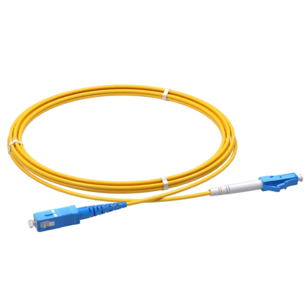
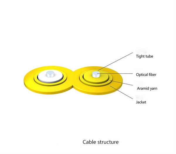
Temukan daftar Supplier, Pabrik, Importir, Distributor dan Toko Kabel Patch Cord untuk wilayah Indonesia . Update setiap hari, harga kompetitif dan layanan terpercaya. High performance and high quality connectors cable assembly are required for next generation optical networks to assure long term reliability for demanding applications such as FTTx, DWDM, 100G, CATV and etc. The connector assemblies are IEC, Telcordia and RoHS compliant. The termination passed. Prima Akses Digital Indonesia, is a Indonesian local company specialized in fiber optic product development and solution service for network infrastructure. Prima Akses Digital Indonesia, established in 2020, is supported by several partner companies and management which have been experienced in.
[PDF]
of relay protection coordination for a PV power plant connected to the distribution network is presented. In recent years, installation of PV power plants in the distribution network has increased significantly. I.
[PDF]

The SEL-221F Relay uses positive-sequence memory voltage polarized mho distance elements for phase and ground distance protection. These elements expand in proportion to the source impedance to provide more resistive fault coverage than self-polarized mho elements. VAMP 221 arc protection system components. Central unit VAMP 221. I/O units VAM 12L / VAM 12 LD, VAM 10L / VAM 10LD, VAM 3L / VAM 3LX and VAM 4C / VAM 4CRL / VAM 4CD 10 1. Arc sensors VA 1 DA, VA 1 EH, ARC SLx. Schneider Electric VAMP range is an arc flash detection and protection pioneer offering fast and reliable devices to improve safety. VAMP 221 significantly reduces the risk of potential personal damage, and material and production losses caused by arc fault. VAMP 221 complies with the latest standards concerning the. Serial communications ports allow local or remote interaction with the relay. 5” high chassis sizes. The report will identify methodology behind these practices, present issues raised by the integration of microprocessor relays and the internal logic and external communication configurations, ying. In the design of electrical power systems, the ANSI Standard Device Numbers denote what features a protective device supports (such as a relay or circuit breaker).
[PDF]

In this guide, we'll explore what protection relays are, how they're classified, the types available, and how they work with instrument transformers to create secure zones of protection. What Is a Protection Relay?. Protective Relay Definition: A protective relay is an automatic device that senses abnormal conditions in electrical circuits and triggers actions to isolate faults. Types of Protective Relays: Protective relays are categorized by their mechanism (electromagnetic, static, mechanical) and function. This article covers various types of protective relays, such as overcurrent, directional, and differential relays, highlighting their operating characteristics and applications in electrical systems. They don't just protect equipment; they ensure safety, prevent downtime, and save lives. A protective relay is a device that detects the fault and initiates the operation of the circuit breaker to isolate the defective element from the rest of the. The rectangular devices are test connection blocks, used for testing and isolation of instrument transformer circuits.
[PDF]
In the ring distribution network, differential relays, which rely on communication between the protection relays, are used for the underground cable protection. To guarantee cable protection when communication is failed, an auxiliary protection by using directional overcurrent. The use of ring circuits in 6 – 35 kV distributed electrical networks can improve the reliability of power supply. An increase in the load power and the share of distributed generation and renewable energy sources causes the redistribution of the power flow during the operation of an electrical. The selected protection principle affects the operating speed of the protection, which has a significant im-pact on the harm caused by short circuits. The faster the protection operates, the smaller the resulting ha-zards, damage and the thermal stress will be. Further, the duration of the voltage. ABSTRACT: Over current protection is the simplest form of power system protection of distribution line. In. The purpose of this study is to investigate the coordination of overcurrent relay in different types of the distribution network, which are radial, ring, and interconnected distribution system during line to ground fault occurrence at the bus. Usually, this refers to medium-voltage networks, since they are protected by numerical relay devices, as opposed to low-voltage networks, where utility operators allocate.
[PDF]
The relay block comprises the two protection units, phase protection unit and earth protection unit. When the value of the current in any of the phases is greater than the pick up value, the phase protecti.
[PDF]

The total interruption time for a modern high-voltage SF6 circuit breaker is typically between 40 to 60 milliseconds on a 50Hz grid, or 2 to 3 cycles. This is the total time from the trip signal to the final arc extinction, a critical parameter for grid safety. While knowing the total time is a. When a SF6 circuit breaker (CB) hits its critical low pressure, its fault interrupting capability can be compromised. Most TOs protect against this by either auto-opening the CB prior to reaching the critical low-pressure level or by blocking the CB from tripping (when it reaches the critical. The protected zone is defined and limited by different things depending on the protection function. Definite time delay means that the protection operate time dose not change or depend on the fault type or the fault current magnitude. Instead of oil, air, or a vacuum, a sulfur hexafluoride circuit breaker uses sulfur hexafluoride (SF 6) gas to cool and quench the. Page 1 Content Instruction Manual circuit- breaker GL317 With spring operating mechanisms FK3- 4 Administrator First issue Compiled by Approved by 19- 11- 2012 J. Texier Imagination at work Grid Solutions 04- 2017 D1736EN/03 GE Information 1/10. Page 2 Content Instruction Manual This. A comparison of the time it takes protective devices to operate when certain levels of normal or abnormal current pass through them. LV circuit breaker ratings.
[PDF]
IEC 60255-1:2022 specifies common rules and requirements applicable to measuring relays and protection equipment, including any combination of equipment to form a distributed protection scheme for power system protection such as control, monitoring and process interface equipment . IEC 60255-1:2022 specifies common rules and requirements applicable to measuring relays and protection equipment, including any combination of equipment to form a distributed protection scheme for power system protection such as control, monitoring and process interface equipment . The IEC standard for protection relays plays a vital role in modern electrical power systems. Protection relays are essential devices used to detect abnormal conditions in electrical circuits. These conditions may include overloads, short circuits, or insulation failures. When such conditions are. The testing and verification of relay protection devices can be divided into four groups: Type tests are needed to prove that a protection relay meets the claimed specification and follows all relevant standards. Choose from interactive classroom training and hands-on. To meet this need, the IEC is currently working on the IEC 60255-1xx series of functional standards dedicated to protection relays and protection functions. Before looking at the benefits these standards can provide, let us review some background information.
[PDF]
The electrical quantities that may change under fault conditions include: voltage, current, frequency and phase angle. As the protected components of the electrical systems have changed in size, configuration and their critical roles in the power system supply, some protection aspects need to be revisited (i. the use of protection systems to reduce arc flash energy in distribution systems). This presentation. In electrical engineering, a protective relay is a relay device designed to trip a circuit breaker when a fault is detected. : 4 The first protective relays were electromagnetic devices, relying on coils operating on moving parts to provide detection of abnormal operating conditions such as. The relays detect the abnormal conditions in the electrical circuits by constantly measuring the electrical quantities which are different under normal and fault conditions. A typical. Overcurrent relays are the most common form of protection used to operate only under fault conditions. The relay settings that are selected are often a compromise in order to cope with both overload and. Time-current characteristics, current setting, over current protective schemes, directional relay, protection of parallel feeders, protection of ring mains, Phase fault and earth fault protection, Combined earth fault and phase fault protective scheme, Directional earth fault relay.
[PDF]
Relay protection is the discipline of designing schemes that detect faults, coordinate relays, and isolate equipment without outages. It emphasizes selectivity, coordination, fault response, and system behavior rather than individual relay devices. The main relay protection functions (overcurrent, directional, differential, distance, etc. ) and network communication systems (SCADA, RTUs, digital and analog inputs and outputs, IEC 61850, etc. ) are briefly explained in this technical article. Table of contents: 1. Protection systems Protection. Electromechanical protective relays at a hydroelectric generating plant. The relays are in round glass cases. The rectangular devices are test connection blocks, used for testing and isolation of instrument transformer circuits. In electrical engineering, a protective relay is a relay device. transmission line faults through the use of communication-assisted protective relaying. These conditions may include overloads, short circuits, or insulation failures. It functions as a watchdog by constantly surveying multiple system components including voltage, current, frequency, and phase angle.
[PDF]

Relay testing involves verifying the correct operation of protective relays under various fault conditions. This process ensures that the relays provide accurate and timely tripping signals to circuit breakers, isolating the faulty sections of the electrical network. Protective circuit functional testing, including lockout relay testing, must take place immediately upon installation, every 2 years thereafter, and upon any change in wiring. If applicable, documentation is required detailing how verified protection segments overlap to ensure there is not a gap. Relay systems protect high-voltage equipment and transmission lines to ensure safe, stable systems. Although failure of a protective relay system may have severe local or regional impacts, most protective relay systems are not required to operate to prove they are in working order. Ensuring that. Relay testing and maintenance are crucial aspects of ensuring the reliability and stability of power systems. Protective relays play a vital role in detecting and isolating faults in electrical networks, thereby safeguarding expensive equipment and preventing cascading failures. This guide provides recommended. Protective relaying aims to stop that chain reaction before it starts, detecting problems instantly, cutting off the affected section, and keeping the rest of the system stable and safe. A good preventive maintenance program ensures the protection system is in functioning order.
[PDF]
Download Sample Report Now: Global Protective Relays Market Size, Share, Trends & Forecast 2026-2034 The following comparison highlights how leading players differentiate across scale, strategy, and regional dominance. Protective relays are electrical devices that are designed to detect abnormal conditions in power systems and isolate the affected part of the system. Insight: Global leaders dominate through scale, while niche innovators gain. These companies offer protective relay devices for electrical systems, protecting them from overloads, short circuits, and other electrical faults. *Disclaimer: List of key companies in no particular order Latest Company Updates: October 2023- The PJM Board of Managers has permitted some. Over Current Relay (OCR): Operates when the current value at the location where the protective relays are installed exceeds the set value. There are two types of elements that trigger the overcurrent protective relays: dimensional elements and instantaneous elements. The dimensional element. The global protective relay market is expected to reach USD 3. 9 billion by 2030, up from an anticipated USD 2. 7% over the forecast period. The shift from traditional relays to advanced, software-driven systems in protective relays brings enhanced reliability. Moreover, according to Consegic Business Intelligence, Protective Relay Market size is estimated to reach over USD 5,093. 8% from 2025 to 2032.
[PDF]
In electrical engineering, a protective relay is a relay device designed to trip a circuit breaker when a fault is detected. : 4 The first protective relays were electromagnetic devices, relying on coils operating on moving parts to provide detection of abnormal. The rectangular devices are test connection blocks, used for testing and isolation of instrument transformer circuits. Its main purpose is to safeguard electrical equipment like transformers, generators, and transmission lines from damage due to. Eaton's protective relays provide you with unique microprocessor-based devices that eliminate unnecessary trips, mitigate arc faults, protect motors and breakers, and provide system information to help you better manage your system. Our predictive diagnostic solutions include non-destructive testing. Protective Relay Definition: A protective relay is an automatic device that senses abnormal conditions in electrical circuits and triggers actions to isolate faults. Types of Protective Relays: Protective relays are categorized by their mechanism (electromagnetic, static, mechanical) and function. Combines protection, sensors, control power, and circuit breaker in a single package Typically added to a breaker close circuit to prevent accidental reclosure after a trip. Three fundamental components required for each circuit breaker. This prevents damage to equipment, reduces downtime, and safeguards.
[PDF]
Protection is accomplished by application of a definite time overcurrent option. Current setting is greater than full load current but is lower than the motor starting current. Should a motor stall whilst running, or fail to start, due to excessive. When a motor starts, it can draw 6-8 times its full-load current for a brief period, creating significant challenges for circuit protection, voltage regulation, and system capacity planning. Understanding motor starting characteristics is essential for proper breaker sizing, motor protection relay. These time-overcurrent elements support the IEC and U. (IEEE) time-overcurrent characteristics. Electromechanical disc reset capabilities are provided for all time-overcurrent elements. protection and fault clearance in abnormal situations. The main features of the motor relay include thermal overload protection, motor start-up time supervision, locked rotor protec ion, and protection against too frequent motor starts. Addi ionally, differential protection can also be included. In order to prevent damage to the contactor, the maximum peak let-through current (Ip ) and maximum clearing energy (I2t) (amps2 seconds) of the fuse must be less than the equivalent ratings for the contactor. The clearing time and let-through characteristics of the fuse must be considered when.
[PDF]