In practice, the bit error rate of a system for optical data transmission (e. a fiber-optic link) can be increased by noise influences (particularly in the receiver, but also in the transmitter and in amplifiers), by optical losses, and chromatic and other types of dispersion. Bit Error Rate (BER) is a critical performance metric in optical communications that measures the number of errors occurring in a transmitted data stream over a certain period. It is defined as the ratio of the number of bits received in error to the total number of bits transmitted. It quantifies the frequency of channel errors, which are often caused by interference such. Unlock AI-driven, actionable R&D insights for your next breakthrough. As optical links are increasingly used for high-speed data. A high Bit Error Rate (BER) in 800G optical modules is a multifaceted and complex issue that requires a systematic approach for step-by-step troubleshooting. It is recommended to follow an order from simple to complex to efficiently locate and resolve the problem. Use the command line interface. ted for improvement of BER in fiber optic communications. The developed scheme has been tested on optical fiber systems operating with a non-return-t -zero (NRZ) format at transmission rates of up to 10Gbps.
[PDF]
Most systems operate by transmitting in one direction on one fiber and in the reverse direction on another fiber for full duplex operation. Most systems use a "transceiver" which includes both transmission and receiver in a single module. The optical module serves as a crucial component in optical fiber communication systems, operating at the physical layer, which is the lowest layer in the OSI model. Its primary function is to achieve optoelectronic conversion by converting electrical signals into optical signals and vice versa. Operating at the physical layer of the OSI model, optical modules are core devices in optical. An optical module is a typically hot-pluggable optical transceiver used in high-bandwidth data communications applications. Optical modules typically have an electrical interface on the side that connects to the inside of the system and an optical interface on the side that connects to the outside. In the world of fiber optic communications, optical transceiver modules play a pivotal role as interfaces that convert electrical signals to optical signals and vice versa.
[PDF]
In a 256-GPU GH200 cluster, each GH200 corresponds to 9 800Gbps optical modules, with each module delivering 100GB/s over two NVLink 4. The key difference between the DGX GH200 SuperPod and the DGX H100 SuperPod is that both intra-node and inter-node connections use. Since optical modules are primarily used for inter-switch and long-distance links, the main optical module demand in GH200 clusters comes from the L2 NVLink network and the IB network. Estimating Optical Module Count in GH200 Clusters Analysts and technical sources have estimated the number of. The GH200 integrates the H200 GPU (the main differences between H200 and H100 are memory size and bandwidth) with the Grace CPU, with one Grace CPU paired with one H200 GPU. 0 connections between GPUs, GH200 also uses NVLink 4. 0's 900GB/s. The NVIDIA GH200 Grace Hopper™ Superchip is a breakthrough processor designed from the ground up for giant-scale AI and high-performance computing (HPC) applications. The superchip delivers up to 10X higher performance for applications running terabytes of data, enabling scientists and researchers.
[PDF]
Optical modules convert electrical signals into light to move data quickly and reliably in AI systems, enabling fast and smooth data processing. Using advanced optical modules boosts AI system speed and bandwidth, helping handle large data loads with low delay and high efficiency. The optical module serves as a crucial component in optical fiber communication systems, operating at the physical layer, which is the lowest layer in the OSI model. Its primary function is to achieve optoelectronic conversion by converting electrical signals into optical signals and vice versa. Operating at the physical layer of the OSI model, optical modules are core devices in optical. That is, metal medium communication represented by coaxial cables and network cables is gradually being replaced by optical fiber media. Among various optical module form factors, SFP (Small Form-Factor Pluggable). These compact modules are the high-speed, high-bandwidth lifelines connecting the massive compute and storage resources AI demands. Understanding their role is key to building efficient, scalable AI systems.
[PDF]
To tackle these challenges, Huawei has launched its StarryLink optical modules for data center networks, featuring three robust capabilities: spanning, stable, and secure, delivering a "3S" high-quality network experience for enterprises. [Barcelona, Spain, March 4, 2025] At MWC Barcelona 2025, Huawei introduced the StarryLink optical modules, aimed at creating a network experience with "3S" quality (Spanning, Stable, Secure). This announcement occurred during the data center session titled. In the AI era, data center network interconnection presents new challenges for optical modules, requiring significant improvements in transmission distance, O&M efficiency, and interconnection security. To address these demands, Huawei has launched the StarryLink optical module brand. Huawei's optical communications products are widely deployed in data centers, metropolitan area networks, long-haul.
[PDF]
Learn how to extend GDB with optical signal breakpoints for efficient photonics chip debugging and testing with practical implementation steps. Debugging photonics chips requires specialized tools that can monitor and analyze optical signals alongside electronic ones. Legal status (The legal status is an assumption and is not a legal conclusion. Google has not performed a legal analysis and makes no representation as to the accuracy of the status listed. ) Current Assignee (The listed assignees may be inaccurate. These modules leverage advanced signal processing, modulation, and high-speed interfaces to provide high bandwidth, low latency, and reliable performance. Standard debugging tools like. modules used with NADDOD switches, for reference by technicians and users. For any questions, please contact NADDOD. When testing PRBS, there are 3 test nodes: MAC ----> PHY. In view of this, the embodiments of the present invention expect to provide an optical module commissioning device, commissioning method, and electronic equipment to solve the time-consuming technical problem of manually commissioning a DSFP optical module through a commissioning device in. Optical detection chips serve as essential components in intelligent optical computing systems, demonstrating crucial significance. These chips exhibit high sensitivity and broad wavelength response ranges, enabling precise optical signal reception and conversion while providing reliable data input.
[PDF]
HUAWEI WDM replacing the optical module video shows you how to replace an optical module. HUAWEI WDM Documentation:. This section describes how to install an optical module. The method used to install a copper transceiver module is the same, except that the copper transceiver module connects to a network cable instead of optical fibers. Never look directly into an optical module or the ends of optical fibers. Step 2: Take out the optical module, ring and label up, the gold finger is facing down, Note that the right. To avoid component damage caused by improper operation, we should strictly follow the following procedures for installation. 6 Parts Replacement l The BMC serial port, SYS serial port, and GE electrical port are standard RJ-45 ports, and their cables can be installed in the same way.
[PDF]

The actual number of optical modules used primarily depends on the following factors. Discrepancies in Calculating the Ratio of Optical Modules to GPU-The Varying Usage Quantity Due to Different Networking Architectures. Network Card Model. GPUs such as the A100, H100, and upcoming GH100 require high-speed optical interconnects to link thousands of GPU nodes, enabling large-scale AI model training and inference. Network Card Model It mainly includes two network cards, ConnectX-6. Traditional optical transceivers, especially in 400G and 800G deployments, generate significant heat and demand substantial power just to keep the lights blinking. 1) NIC Models Mainly includes two types of network cards, ConnectX-6 (200Gb / s, mainly used with the A100) mainly used optical modules are MMA1T00-HS (200G Infiniband HDR QSFP56 SR4 PAM4 850nm 100m) and ConnectX-7. Two complementary approaches are used to grow these systems: scale-up (tightly coupling many accelerators as one unit) and scale-out (networking multiple units across racks or clusters). In both cases, optical connectivity is playing an increasingly vital role. Below, we explain the trends in. While the industry-standard OSFP (Octal Small Form-Factor Pluggable) module has successfully enabled 400Gbps, 800Gbps, and 1. 6Tbps optical pluggable modules , it is limited to 32 modules per Rack Unit (RU), typically requiring 2 RUs to achieve 102. 4Tbps and 4 RUs to reach 204. 8Tbps of switching.
[PDF]
In order to save power within the module, optical modules have been made that used the digital interface definition, such as the CEI, but without retiming the signals within the module.OverviewAn optical module is a typically hot-pluggable optical transceiver used in high-bandwidth data communications applications. Optical modules typically have an electrical interface on the side that connects t. There have been multiple variants of the electrical interface of optical modules that have been used over the years. The earliest forms of optical modules had an analog electrical interface. In the transmit dir. Many different forms of optical modulation and multiplexing have been employed in optical modules. The most common modulation technique historically has been or NRZ.
[PDF]
The GE optical interface (100/1000 Mbit/s auto-sensing) transmits and receives services at 100 Mbit/s or 1000 Mbit/s. It must be used with an Optical Fiber, GE eSFP Optical Modules, or FE SFP/eSFP Optical Modules. This document describes hardware components of the AR, including the cabinet, chassis, power supply facilities, fan modules, cards, cables, and pluggable modules for interfaces. You can find useful information about AR hardware components from this document. This document describes hardware. mory. Huawei AR1220F-S enterprise router is next-generation, enterprise-class routers based on the Huawei proprietary Versatile Routing Platform (VRP). Figure 1 shows the appearance of Huawei Router - AR1220F. This document describes hardware. Troubleshooting Slow Internet Access Issues on AR Routers Troubleshooting Internet Access Failures Through AR Routers(V300) Troubleshooting IPSec Issue Troubleshooting AP Join Failures TCP/IP Overview L2TP VPN troubleshooting IP Routing Basics How to Log In to an AR Router Through the Web and.
[PDF]
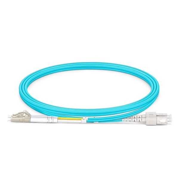
Single-mode optical modules are best for long distances and fast speeds. They use a thin fiber core. Think about distance, speed, fiber you have. Based on the transmission mode of optical fibers, optical modules can be categorized into single-mode optical modules and multi-mode optical modules. What are the differences between them? And in which scenarios are they respectively applicable? I. Differences Between Single-Mode and Multi-Mode. The secret lies in fiber optic technology, and understanding the basics—1-core, 2-core, Single Mode (SM), and Multi-mode (MM)—is key to mastering this field. Definitions · 1-core vs. 2-core o In optical modules, "core". This guide breaks down practical differences—core geometry, wavelengths, connector types, performance limits, cost trade-offs, and ideal use-cases—so you can pick the right optical modules with confidence. Single-mode fiber uses a 9/125 µm core/cladding structure that supports only one propagation. The optical module (opTicalmodule) is composed of optoelectronic devices, functional circuits and optical interfaces. The optoelectronic devices include two parts: transmitting and receiving. Correctly distinguishing single-mode and multi-mode.
[PDF]

We'll examine Linear Pluggable Optics (LPO) and Linear Receive Optics (LRO) as cost-effective, low-power alternatives, discuss advanced cooling solutions tackling the heat challenges of high-speed modules, and explore game-changing paradigms like Co-Packaged Optics . We'll examine Linear Pluggable Optics (LPO) and Linear Receive Optics (LRO) as cost-effective, low-power alternatives, discuss advanced cooling solutions tackling the heat challenges of high-speed modules, and explore game-changing paradigms like Co-Packaged Optics . Push open the door to the data center, and amidst the humming server racks, countless thin optical fibers are carrying massive amounts of data. At the source of these fibers, a component the size of a fingernail — an optical chip—determines the performance ceiling of the entire communication. Push open the door to the data center, and amidst the humming server racks, countless thin optical fibers are carrying massive amounts of data. Coherent technology facilitates long-distance, high-speed transmission with exceptional signal quality. Linear drive pluggable optics (LPO).
[PDF]
Short answer: Usually yes, you use them in pairs, but the “pair” can be a media converter on one end and a fiber switch (or SFP in a switch) on the other, as long as both sides speak the same speed, wavelength, and optical mode. Mixing single-mode and multi-mode transceivers creates major optical and hardware problems. This leads to unreliable network performance. Here's why: Light source & beam profile: SM lasers are narrow and Coherent; they couple efficiently into a 9 µm core. MM VCSELs/LEDs produce a broader beam. Single-mode optical modules are best for long distances and fast speeds. They use a thin fiber core. Picking the right optical module depends on your network needs. The sfp transceiver single mode typically utilizes laser diodes as the light source and operate at wavelengths of 1310nm or 1550nm. The key is opposite directions use opposite wavelengths, so A must face B—AA or BB will not work. Other BiDi pairs exist (e. Single-mode fibers support a wide band and large transmission capacity, and are used for long-distance. o In optical modules, "core" refers to the light-transmitting channel in the fiber. A 1-core module uses a single fiber core for data transmission, while a 2-core module uses two cores. o Think of a highway. A 1-core fiber is like a single-lane road—only one car (or data signal) can travel at a.
[PDF]
A Thin-Film Filter (TFF) is an optical device that uses multiple layers of dielectric coatings deposited on a substrate to selectively transmit or reflect specific wavelengths of light. It is a fundamental component in modern optical communication systems. The Z-Block is a core optical component used in wavelength division multiplexing/demultiplexing (WDM) systems. Structurally, it is typically composed of several integrated optical elements, including collimating lenses, rhomboid prisms, and specially designed optical mirrors. TFFs are widely used as. The Process Technology of Optical Coating: Applications of TFF in Optical Communication Optical coating technology has revolutionized the way we enhance the performance and durability of optical devices, particularly in optical communication systems. As the demand for high-speed internet and. WDM (Wavelength Division Multiplexing) is a technology that expands the optical fiber transmission bandwidth and improves network transmission capacity by transmitting multiple optical signals of different wavelengths in the optical fiber. TFF (thin film filter) and AWG (arrayed waveguide grating). A thin film resonant cavity filter (TFF) is a Fabry-perot A cavity is formed by using multiple reflective dielectric thin film layers. The TFF works as bandpass filter, passing through specific wavelength and reflecting all other wavelengths. The cavity length decides the passing wavelength.
[PDF]

800G optical modules provide 2× bandwidth and ~30–40% better power efficiency per bit than 400G, while reducing fiber count significantly. However, 400G remains more cost-effective for enterprise workloads, and 1. 6T is still in early deployment stages primarily targeting AI-scale data. 400G, 800G, and 1. 6T is growing exponentially. This surge is driving technological upgrades in optical modules toward higher data rates. NADDOD, the leading optical modules. Developments in three distinct areas are needed for 800G deployment: optical modules and direct attach copper (DAC) cables, switch ASICs, and 800GE standardization. Not all these need to be fully delivered for data center operators to benefit from 800G upgrades. By understanding the key. Choosing between 400G and 800G optical modules depends on your workloads, scale, and budget. This guide breaks down the differences, use cases, and deployment advice in simple but detailed terms. What are Optical Modules? An optical module (or optical transceiver) is a pluggable device inserted. Today's data center Ethernet switches are essentially optical communication devices, as the entire system operates on optical transmission principles. This article will explore the evolution of modules' speed and form factor from 400G to 1.
[PDF]