MDC virtualizes one S7500X switch into multiple logical switches, enabling multiple services to share one core switch. The 1:N virtualization maximizes switch utilization, reduces network TCO, and ens.
[PDF]

This is a walkthrough for the TASK Master side mission in Borderlands 4. Read on to follow the objectives and clear the mission, as well as how to replace power core. TASK Master is part of a questline that starts with The Kairos Job. A core switch in networking serves as the high-capacity backbone, italic centralizing data flow and ensuring efficient communication between different network segments. Simply put, it's the kingpin that keeps your network humming. You may also want to know: Can a Nintendo Switch Play DS Games? ·. To prevent electrostatic damage (ESD) to electronic components, you must be sure that you are grounded while handling electronic components. Components include, but are not limited to, all switch modules. Connect the switch to the facility earth ground. Attach an ESD wristband to your arm and be. Unless you power on layer 3 switch; specifically 3650, you will not be able to configure it or even access the command line interface (CLI). In this post, I will show you how to power on Layer 3 switch in packet tracer; both the steps you need to take and a video demonstrations of the process Here. In such high-capacity ethernet networks, switches are crucial as they direct data and transmit signals to the addressed devices. There are different types of enterprise switches that perform various roles in these layer-based or hierarchical ethernet networks. Complete The Kairos Job, Free for the TASKing, and TASK and Ye.
[PDF]
To replace an electrical switch, expect to spend about $80 to $120 on average. It's all relative, but $23k for a pair of core switches is cheap IMO. Cisco would try to charge A LOT MORE. I removed all. FI per port to connect to Nexus switches. 9Ghz, 6Core Broadwell DE CPU128GSSD,32GDRAM REMANUFACTURED. Check CORE SWITCH price from the latest Cisco price list 2022. Our core switches are EOL and have been for a long time. I need 5 core switches for $15,000 for a mid-size organization with multiple locations. Suggestions? Want to add to the discussion? Post a comment! [–] bitslammer Infosec/GRC 21 points [–] Sr. Sysadmin How many ports? What kinds of ports? L2. Unlock exclusive savings on 5/9/26 at 9am PT. Did You Find It? Save this search Request a server item Cisco Catalyst 9200CX-8P-2E Compact Switch, 8-Port PoE+, 240W, Network Essentials. MikroTik CRS504-4XQ-IN Cloud Router Switch 650MHz 4xQSFP28 Compatible with 40G. There are no specific requirements for this document. The information in this document was created from the devices in a specific lab environment. it's an old 3560 catalyst with a pretty basic configuration.
[PDF]
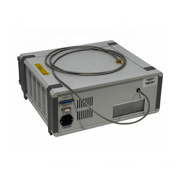
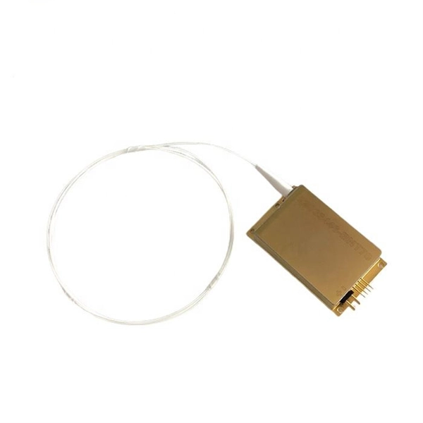
Lasers, modulators, and photodiodes form the core architecture of optical transceivers, enabling light-speed communication across global networks. Lasers generate the optical carrier. Modulators encode digital information. An optical transmitter is a crucial device used in fiber optic communication systems. Its primary function is to convert electrical signals into optical signals It involves modulating electronic system data and transforming it into light pulses using a laser or LED, and sending the pulses through. The optical transmitter and the optical receiver are the core components that enable this process, forming the electronic-to-optical and optical-to-electronic gateways necessary for modern, high-capacity data transmission. It takes data from an electronic system, uses a laser or LED to modulate that data into pulses of light, and then sends those pulses down the fiber. Together, lasers, modulators, and. At the core of a fiber optic system is the optical fiber – a flexible, transparent strand of glass, thinner than a human hair. Optical fiber is formed by drawing glass or plastic to a diameter slightly thicker than that of a. What are the main elements of an optical transmitter? Data decoder/demodulator, electrical interface, detector, optical interface.
[PDF]
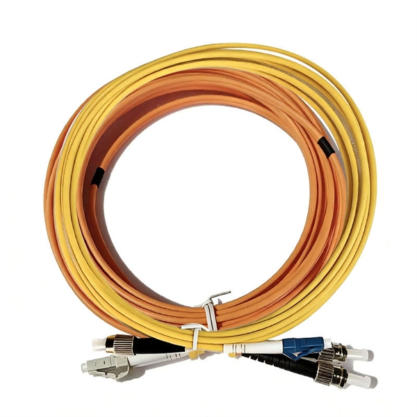
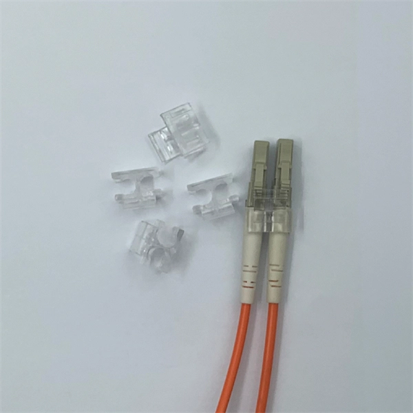
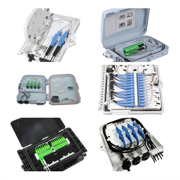
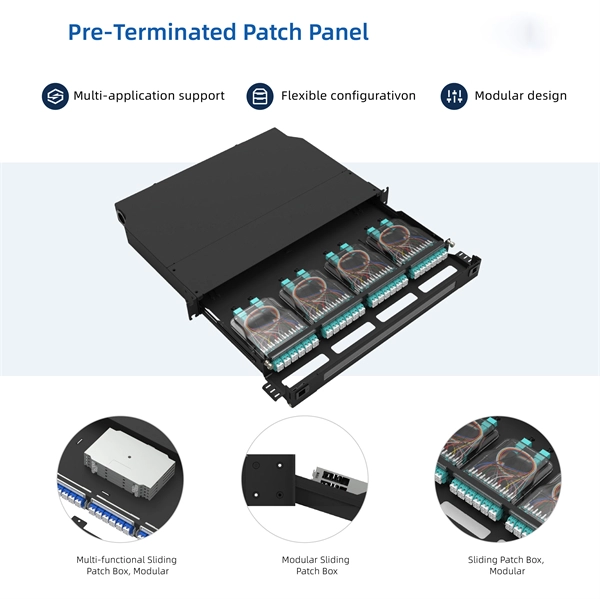
A fiber pigtail is typically a fiber optic cable with one end factory pre-terminated fiber connector and the other exposed fiber. It is usually suitable for field termination using a mechanical or fusion splicer. Executive Summary: A fiber optic pigtail is one of the most commonly specified yet least understood components in structured cabling. Get the wrong connector type, the wrong polish, or skip proper fusion splicing technique—and you're looking at elevated signal loss, increased back reflection, and a. A fiber optic pigtail is a short length of optical fiber —typically 0. The connector end is polished and tested under factory conditions, ensuring low insertion loss and high return loss. The connector end can be linked directly to network equipment, while the exposed end can be spliced to another fiber optic cable. Compared with quick termination or epoxy and polish connections placed on the field. Fiber optic pigtails are short, single, or multi-strand pieces of optical fiber cables with a connector on one end and exposed fiber on the other end. This essential function of pigtail fiber is.
[PDF]
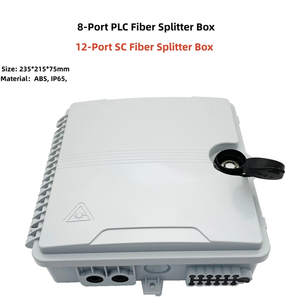
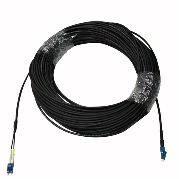
The drop cable connects your home, the patch panel organizes the network, the splice keeps connections seamless, and the optical splitter shares the signal with your neighbors. The fiber drop cable is what makes a true fiber-to-the-home (FTTH) connection possible. It's the final link in the chain that ensures you're getting the full, unfiltered power of fiber internet, not a mix of fiber and older technology. From the street to your living room, every piece of the fiber. To begin, the standard definition of splicing in optical fiber is joining two fiber optic cables together. The other, more common, method of joining fibers is called termination or connectorization. Splicing is most commonly used in the field but has application in cable assembly houses. Infield. In many applications of fiber optics, it is necessary to connect fiber ends (terminations) in some way such that light from one fiber can get into the other fiber without losing too much of its optical power. This creates a permanent and low-loss connection. Both techniques have their advantages and are suited for different applications, but understanding which method to use can greatly impact the network's. Many installations involve splitting the fibers in a cable or dropping a small fiber count cable from a large backbone cable. Backbone cables of 144-288 fibers are common and larger ones are becoming more common too. Drop cables are often only 2-12 fibers, meaning most fibers are continuing.
[PDF]
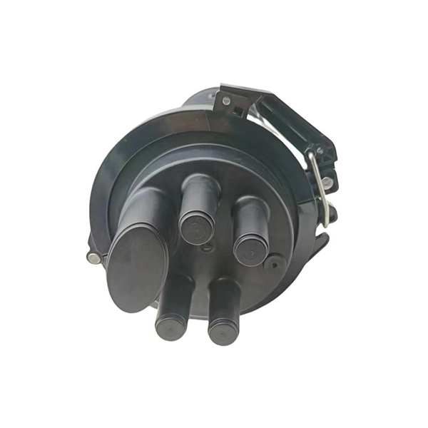
Dual fiber modules use two fibers. They are easier to set up and give steady communication. They use a thin fiber core. They cost less and are. IntroductionEngineers, purchasing managers and installers often see the terms Transceiver, optical module and fiber optic module used interchangeably — and that causes confusion. This article answers the question directly and precisely: what each term usually means, where they overlap, and what. Optical modules and fiber optic transceivers are both essential components in fiber optic communication systems. Optical module: belongs to a. However, there are still many things that need to be paid attention to about how to link the optical fiber and the optical module. An optical module is a functional module, or an accessory. It is a passive device that cannot be used alone. It can only be used in switches and devices with optical.
[PDF]
Fiber optic cables can be run anywhere from 2 kilometers to over 100 kilometers without signal regeneration, depending on the cable type and application. Fiber optic cable transmission distance is determined by two primary physical factors that affect signal quality as light travels through the fiber medium. The greater the distance, the greater. In this blog, I will discuss the fiber optic cable distance, the effect factors, how to choose the right fiber optic cables, and how to compare the transmission distances of single-mode and multimode fiber optic cables. Single-mode fiber (SMF) supports distances up to 40-100+ kilometers for standard applications, while multimode fiber (MMF) is typically limited. Fiber optic cables are the backbone of modern communications, enabling high-speed data transfer over vast distances. Unlike traditional copper cables, fiber optic cables use light to transmit data, resulting in faster speeds and greater bandwidth capabilities. Chromatic dispersion This is a key factor affecting single mode fiber distance. While this technology offers higher speeds and longer distances than traditional copper wiring, physical limitations impose distance constraints. Light pulses degrade as they travel over long spans, primarily.
[PDF]
In, a single-mode optical fiber, also known as fundamental- or mono-mode, is an designed to carry only a single of light - the. Modes are the possible solutions o. In 1961, while working at American Optical published a comprehensive theoretical description of single mode fibers in the. At the Corn.
[PDF]
In this post, you'll learn about the differences between one-tailed and two-tailed hypothesis tests and their advantages and disadvantages. I include examples of both types of statistical tests. In my next post, I cover the decision between one and. The design choice of double vertical fins and single vertical fins is not just for appearance considerations, but is deeply affected by the performance and purpose of the aircraft. This article will provide an in-depth analysis of the scientific principles and design logic behind the design of dual. Understanding the difference between one-tailed and two-tailed tests is crucial in determining the directionality of our hypotheses and the significance of our results. Join us as we unravel the intricacies of these tests and discover their applications in educational research. One-tailed tests look for an effect in a specific direction, such as an increase or decrease, while two-tailed tests consider effects in both directions. The alternative hypothesis parameter, commonly referred to as “one-tailed” versus “two-tailed” in statistics, defines the expected direction of the difference between control and treatment groups. In a two-tailed test, we assess whether there is any difference in mean values between the groups. The consequences in this example are extreme, but they illustrate a danger of inappropriate use of a one-tailed test.
[PDF]
The layer 2 switches collect the data from core switches, identify the type of data packet and the address of the access device. Selective routing and switching take place at the distribution layer. Those new distribution switches will have L3 redundant connections to the CORE switches running EIGRP so this will provide us high availability and load balacing. The connection between these distribution switches is going to be a L3 link (Cisco recommendation) in order to summarize our networks to. · Layer Positioning: The data link layer (Layer 2) of the OSI model, realizing local forwarding of data frames based on MAC addresses. · Core Task: Establishing direct interconnections between devices within a local area network to ensure efficient communication within the same network segment. ·. Layer 2 Switch is a form of Ethernet switch that switches packets by looking at their physical addresses (MAC addresses). These switches operate at the data-link layer (or layer 2) of the Open Systems Interconnection (OSI) reference model. At Layer 2, edge switches use media access control (MAC) addresses to manage traffic within a local area. The core layer is the backbone of the network. The distribution layer connects the access layer to the core layer. When designing a campus LAN, you may. Physical Layer - Physical layer of TCP/IP model is responsible for physical connectivity of two devices. It contains multiple input/output ports.
[PDF]
This document is intended for network engineers responsible for switch configuration and management. You should be familiar with basic Ethernet knowledge and have extensive experience in network deployment and management. The symbols that may be found in this document are defined. S7700&S8700&S9700&S12700&S16700 Series: Access product manuals, HedEx documents, product images and visio stencils. Symbol Description Indicates a potentially hazardous situation which, if not avoided, could result in equipment damage, data loss, performance deterioration, or unanticipated results. NOTICE is used to address practices not related to personal injury. Supplements the important information in the. Page 1 Quidway S7700 Smart Routing Switch V100R006C00 Configuration Guide - SPU Issue Date 2011-07-15 HUAWEI TECHNOLOGIES CO. Page 2 All other trademarks and trade names mentioned in this document are the property of their respective holders. Notice The purchased products, services and. line starting with the # sign is comments. In device configuration, use the existing interface numbers on devices. To ensure device security, use ciphertext when configuring a password and change the password periodically.
[PDF]
Stimulated Brillouin scattering (SBS) is often an unwanted loss mechanism in both active and passive fibers. Highly multimode excitation of fibers has been proposed as a novel route toward efficient SBS suppression. Here, we develop a detailed, quantitative theory which confirms this proposal and. To keep a smooth output beam, most techniques for mitigating optical nonlinearities are restricted to single-mode fibers. Moving out of the single-mode paradigm, we show experimentally that wavefront-shaping of coherent input light that is incident on a highly multimode fiber can increase the power. In high power applications of multimode optical fibers such as high power beam delivery and optical phase conjugation, the estimation of critical power of stimulated Brillouin scattering is important. Nevertheless, the estimations have taken no account of mode dispersion effect to date. In this. Suppressing Stimulated Brillouin Scattering in Multimode Fiber Amplifier With High Beam Quality Via Full-Field Wavefront Shaping S.
[PDF]
A fusion splicer is a specialized device used to join two optical fibers end-to-end through the process of fusion. By aligning the fibers precisely and applying a controlled electric arc, the fusion splicer melts the ends of the fibers, creating a single, continuous fiber. Fusion splicers are essential for creating low-loss, high-performance fiber optic connections in telecom, FTTH, and data center applications. The best splicers offer core alignment, fast splice times, durable designs, and smart features like cloud syncing and automated calibration. This process minimizes. Fiber splicing is the process of permanently joining two fibers together. Unlike fiber connectors, which are designed for easy reconfiguration on cross-connect or patch panels. There are two types of fiber splicing – mechanical splicing and fusion splicing. It is the technique that has the least insertion loss and almost no back reflection, hence ensuring strong connections over a long period. Fiber optic splicers are.
[PDF]
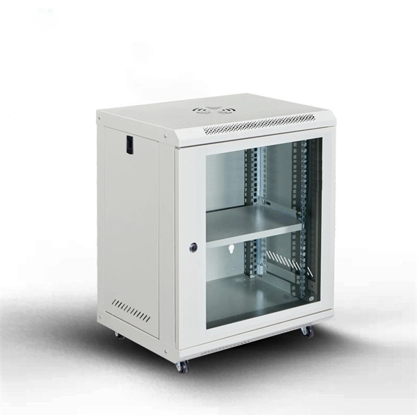
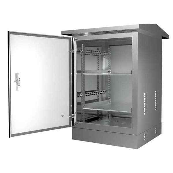
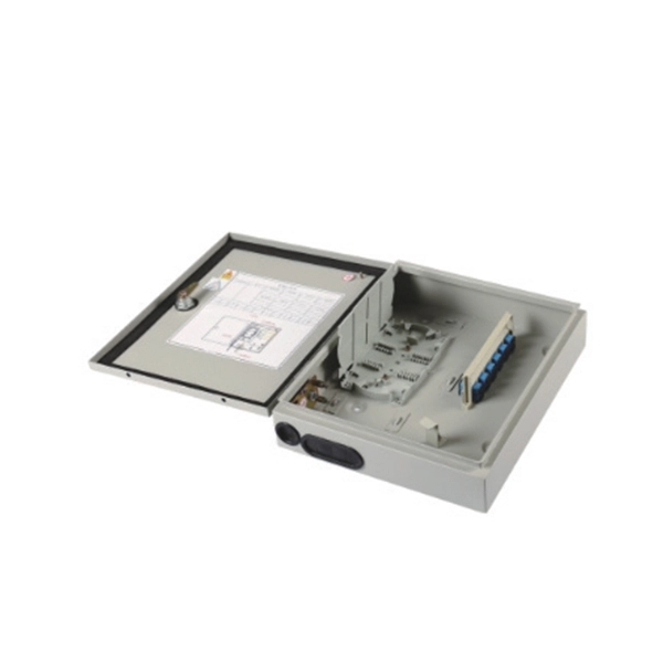
Typically, core switches are Layer 3 switches equipped with robust network management capabilities. They are characterized by numerous ports and high bandwidth, offering greater reliability, redundancy, throughput, and lower latency compared to access and aggregation switches. Engineered to aggregate massive volumes of data from distribution switches, it provides ultra-low latency and maximum throughput to ensure uninterrupted routing and packet. A core switch is a high-capacity network switch that functions as a network's backbone or core layer. It's responsible for accurately routing communication among layers and departments of different sections. In a nutshell, it helps convey vast chunks of data at greater speeds. For a network with. Layer 3 switches are key tools in modern networking, improving both efficiency and flexibility for enterprise networks. Examples include Cisco Catalyst 9300, Ubiquiti UniFi Enterprise XG 24, Juniper EX Series, and FS N5850. These devices enhance performance and security by routing internally at.
[PDF]