A relay protection tester is a core device used to verify the performance of relay protection devices. Its working principle can be summarized as “signal excitation – behavior detection. ”. Circuit principle of relay protection tester 1, input AC220V power output control relay K1 is approved by the insurance into the dual voltage regulator for T1 input carbon brush, through large knob to adjust the power into the isolation transformer T1 T2 (part-time riser), heat flow device points. When the transformer wiring type is Y/Y (Y0), the test wiring is very simple: when testing phase A, the tester IA is connected to the phase A of the high voltage side, and the tester IB is connected to the phase a of the low voltage side. ” The tester has a built-in high-precision programmable power supply, capable of simulating various operating. This handbook covers the code of practice in protection circuitry including standard lead and device numbers, mode of connections at terminal strips, colour codes in multicore cables, dos and donts in execution. The following is a detailed summary. This Playlist is assigned to sessions of protection Relays Principles. First, a description of Simple Functions.
[PDF]
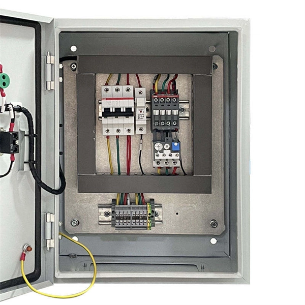
This is not a normal operating temperature, and excessive heat is a serious indicator of an internal fault that could lead to component damage or an electrical fire. Recognizing this heat as a sign of trouble requires immediate attention to prevent potential hazards. Understanding acceptable circuit breaker operating temperatures will help avoid unnecessary replacements and returns. A circuit breaker that is warm to the touch, or too hot to touch, is normally within acceptable operating temperatures. Therefore, it is important to obtain the temperature reading. Every circuit breaker generates heat during normal operation. When electrical current flows through the internal components—contacts, bimetal strips, and terminals—resistance creates thermal energy. This enclosure houses the circuit breakers designed to interrupt current flow when a fault or overload occurs, protecting the entire wiring system. A breaker box is. While a slight warmth can be normal during heavy usage, excessive heat may indicate a serious electrical problem that shouldn't be ignored. In this post, we'll explore: What's Normal for a Circuit Breaker? Circuit breakers are designed to carry electricity safely through your home's circuits. What emerges is a crystal-clear thermal portrait of the distribution box's interior. Like a doctor reading an X-ray, an experienced engineer.
[PDF]
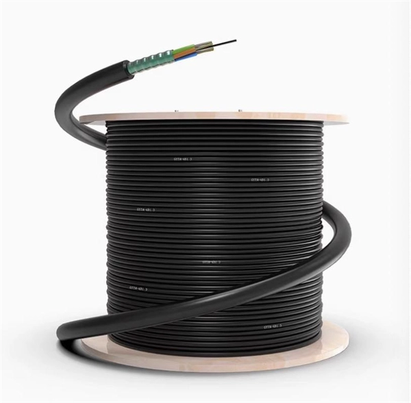
Roadside Telecommunications (RS-TC) Fiber Optic Cable Installation Adjusted Capital Cost Scatter Plot The data used to produce this cost plot are sourced from the ITS Sample Unit Costs Database. These cost data are obtained directly from a variety of sources. Buying fiber optic installation services involves several cost components, with total price influenced by length, location, and access. The main cost drivers include trenching or aerial deployment, materials, labor hours, and any required permits. This guide presents typical price ranges in USD to. Costs to run fiber optic cable vary by distance, trenching needs, cable type and labor rates. This guide outlines typical price ranges and what drives the total cost for U S buyers. Commercial building installations with 100-200 network drops generally range from $15,000 to $30,000. You should account for permit. Typically, per drop fiber cabling prices range from $250 – $1000 per drop depending on the type of fiber (OM2, OM3, OM4, or OM5), multi or single mode, PVC or plenum, average drop length, and also the number of fibers in each cable. Unit cost descriptions have not been.
[PDF]
This diagram highlights media converters, switches, and cable types. Also thanks to Init7 (for the great service), r/FiberOptics and FS for providing me with what I needed to get this setup going. If you find this article useful and you are considering Init7 as your provider you can use my referral code “20700408098” to get CHF 111. - off hardware and also support me. Keeping this page as a placeholder for now. Have any questions? Talk with us directly using LiveChat. A fiber optics network diagram illustrates how high-speed data travels from an internet service provider to end users. By using light signals, fiber optics provide faster speeds and better reliability than. MS Visio has long been the default choice for drafting fiber network diagrams, and with the right stencil libraries it can be used to draw everything from backbone routes to detailed patch panel layouts. When fiber techs look for visio fiber stencils, they are usually solving a very practical. Be among the first to receive important product updates, insights and news. Fiber optic cable is used for everything from demarcation point wiring to network signal distribution to video signal extension. Often, fiber enters the structure to a centralized rack or data room where it is connected to a modem. The modem connects to a network switch which connects each remote.
[PDF]

One-line diagrams and detailed network data (lines, transformers, buses). Short-circuit models, including fault current calculations under various system configurations. Protective relay settings and coordination curves. Historical. presentation of protection and control relaying. The report will identify methodology behind these practices, present issues raised by the integration of microprocessor relays and the internal logic and external communication configurations, ying. Schematic diagrams of protection relays are essential tools for power engineers in the power generation, transmission, and distribution industry. This includes AC schematics and DC schematics and diagrams that prominently feature relaying. There are other equally important types of drawings that are not the subject. Power System Protective Relays: Principles & Practices Presenter: Rasheek Rifaat, P. Eng, IEEE Life Fellow IEEE/IAS/I&CPSD Protection & Coordination WG Chair Jacobs Canada, Calgary, AB rasheek. com IEEE Southern Alberta Section PES/IAS Joint Chapter Technical Seminar - November 2016. Recognized under 2(f) and 12 (B) of UGC ACT 1956 (Affiliated to JNTUH, Hyderabad, Approved by AICTE - Accredited by NBA & NAAC – 'A' Grade - ISO 9001:2015 Certified) Maisammaguda, Dhulapally (Post Via. Kompally), Secunderabad – 500100, Telangana State, India To introduce all kinds of circuit.
[PDF]

Ever wondered how pigtail bolts—critical components in power line fittings—are made? Watch as we take you through the entire manufacturing process step by st. How to Make Electrical Pigtails: This is a basic tutorial on what electrical pigtails are and how to make them. Disclaimer: Always use multiple sources and do your homework before performing any electrical work. Also, make sure all work is done within national and local code. Let's look at how to make pigtail wire links below. Also, it can join several wires to become a single conductor for electrical connections. Let us suppose I had 14 shielded wires to bring into a 15-pin connector where only one pin was available for shield grounds. Imagine how fat a lump there will be if all the shield terminations are located right next to. Bulb to Socket & Component to Connector Cross Reference Guide des spirales de raccord et des douilles Renvois ampoules/douilles et composants/connecteurs Guía de cables flexibles y adaptadores Referencias a bombillas/adaptadores y componentes/conectores NAPA®ECHLIN IGNITION, EMISSION, ENGINE. Pigtail connections are most frequently used to ground a switch or electrical outlet and for electrical devices that need to connect to multiple circuit wires. They also come in handy to lengthen circuit wires that are too short to reach a device. A pigtail is composed of three strands of wire.
[PDF]
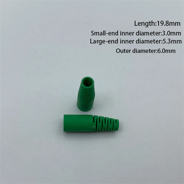
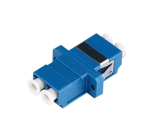
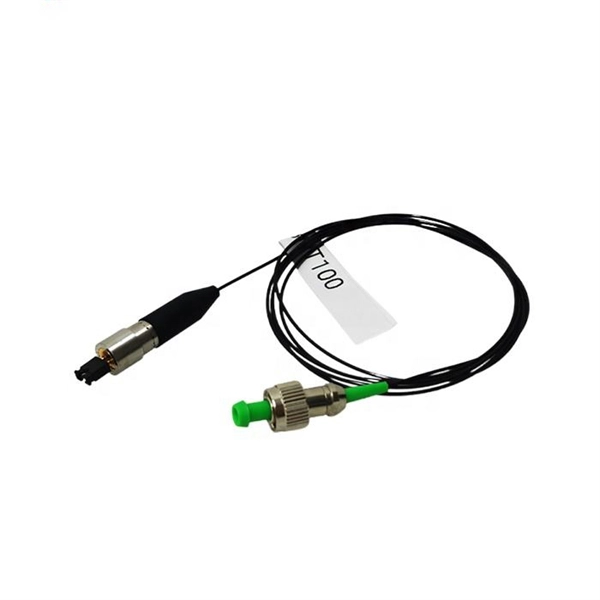
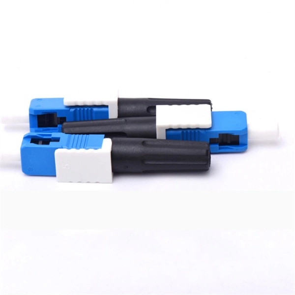
A fiber optic pigtail is a short length of optical fiber —typically 0. 5m to 2m—that has a factory-terminated connector on one end and bare fiber on the other end. The connector end is polished and tested under factory conditions, ensuring low insertion loss and high return loss. They are the bridge between fiber optic cables in the field and the equipment or patch panels that manage them. By combining factory-installed connectors with spliced bare fiber, pigtails ensure that network installers can create fast, reliable, and cost-effective terminations. Without pigtails. What is a Fiber Optic Pigtail, and What Is It Used For? Written by Ben Hamlitsch, trueCABLE Technical and Product Innovation Manager RCDD, FOI A fiber optic pigtail is a type of fiber optic cable with only one end that has a factory-terminated connector and the other end exposed as bare fiber. ) fitted on one end and the other end undressed (for connection through fusion or splicing) to the main fiber optic cable. It is usually suitable for field termination using a mechanical or fusion splicer. Compared with quick termination or epoxy and polish connections placed on the field. Fiber optic pigtail offers an optimal way to joint optical fiber, which is used in 99% of single-mode applications. This post contains some basic knowledge of fiber optic pigtail, including pigtail connector types, fiber pigtail classifications.
[PDF]

Welcome to our channel! In this video, we'll walk you through the process of wiring a home distribution box with a detailed connection diagram. more Welcome to our. Understanding the wiring diagram of an electrical panel box is essential for electricians and homeowners alike, as it allows them to troubleshoot any electrical issues, carry out repairs, or make additions to the system. What is Distribution Board? Distribution board. Hey, in this article we are going to see the Single Phase Distribution Box Wiring Diagram and Connection Procedure. A distribution board or distribution box is where the main power supply is distributed to multiple loads. And all the switching and protective devices are installed in the. That's why having a clear, detailed diagram of your home's distribution board wiring is essential. The diagram. Product Overview Renogy PMS1280 Smart Distribution Box is a centralized direct current (DC) power control hub specially designed for off-grid recreational vehicles, yachts, and motorhomes. The distribution box provides 12 circuit channels for load control as well as voltage and current detection.
[PDF]
Download a comprehensive set of Cable Tray Installation CAD Blocks in DWG format, ideal for electrical engineers, MEP designers, and industrial layout planners. This article shares simple ways to plan your cable trays and wiring. We want to help electrical engineers, technicians, and anyone working with electrical setups build safe and good systems. This collection includes installation details for ladder trays, perforated trays, solid-bottom trays, and wire mesh trays, along with. This guide provides step-by-step instructions on installing a cable tray on a wall, covering different types of cable trays, tools needed, and safety tips. The Ladder Tray features light, rugged, tubular steel construction. It is designed for. In industrial settings, electrical and instrumentation (E&I) cable trays or bridge racks play a critical role in organizing and supporting power, control, and signal cables across facilities. An effective layout ensures safety, minimizes interference, reduces maintenance time, and keeps the overall. ALL TO BE CLEANED WITH A COMMERCIALLY AVAILABLE CLEANSER PRIOR TO ALL MARKERS AFFIXED PRIOR TO INSTALLATION OF ANY CABLE. BONDING JUMPER SHALL BE INSTALLED FOR ELECTRICAL CONTINUITY ACROSS ALL DETAIL AT INTERFACES AND/OR CONDUIT BUSHINGS SHALL INSTALLED FCR ENTRY OF CABLES.
[PDF]
Square D by Schneider Electric offers a unique replacement kit designed to adapt to all brands, different use case scenarios and load type devices such as Load Centers and CSEDs. This kit consists of tw.
[PDF]
In this step-by-step guide, I'll show you how to install different types of rework (old work) electrical boxes in existing drywall. Whether you're adding a new outlet, light switch, or fixture, understanding the right electrical box for the job is crucial for a safe and. They are secured with clamps that are built into the box. Installing a remodeling box is something you can easily do with just a few tools. The step-by-step instructions detail the process of placing a plastic remodeling box in drywall for a. Remodelling an electrical box can seem like a daunting task, but with the right tools and knowledge, it can be a manageable project for homeowners. Learn how to install a distribution box safely and correctly. Covers wiring, placement, standards, and expert tips for a compliant setup. It takes the incoming power and safely distributes it to different circuits throughout your building. Before installing a new electrical box in your home, ensure that the power is turned off at your circuit breaker panel box and use a voltage tester to ensure safety. The process of installing a remodeling box, also known as a gem box, utility box, or handy box, involves removing an existing. Electrical boxes are foundational components of a home's wiring system, serving as protective enclosures where electrical connections are made and devices like switches or receptacles are mounted.
[PDF]
We here listed 10 Corrugated Carton Boxes Manufacturers & Suppliers in Dominican Republic. Suneco Box is a professional Corrugated Boxes Packaging Solution Supplier. Ask. We have a highly trained team, a large inventory of raw materials, production up to 50,000 daily cases, competitive prices and the experience to meet with success at national and international markets. Our company focuses on innovative, cost-effective, and high-quality packaging solutions, that. Standard folding cartons can be customized and enhanced with special materials and our range of processes that ensure a premium finish. International Packaging Company, Inc. main business focus is the manufacturing of specialty packages with its production facility located in Parque Zona Franca. If you are looking for Paper Packaging Boxes Manufacturers and Suppliers in Dominican Republic, you are on the right place. We are a group of companies engaged to the manufacture and marketing of packaging products for the Food, Beverages, Industrial and Pharmaceutical industry. We currently have three product lines. was established in 2007 with the goal of being a leader group for packaging solutions.
[PDF]
This video makes connecting your fiber optic cable to your router a breeze! We'll guide you through the entire process step-by-step, ensuring a smooth and hassle-free experience. Our Experts are helping user's, who are facing issues with their tech gadgets like. In this guide, we'll walk you through how to connect a fiber optic cable to a router safely and efficiently. Why Use Fiber Optic Internet? Before diving into the setup, let's quickly recap why fiber optics are worth the effort: Lightning-fast speeds (up to 1 Gbps or higher). This comprehensive guide combines industry standards with field-tested practices to ensure you achieve a rock-solid. Setting up a fiber internet connection requires understanding key hardware components and following a specific connection sequence to establish your home network. This guide details the necessary physical and digital steps to connect your fiber line and activate your internet service. If you. Connecting a fiber optic cable to a router might seem daunting at first, but with the right tools and a bit of patience, it's a straightforward process. Here's a step-by-step guide to help you through it. Check compatibility: Before you begin, make sure your router supports fiber optic connection. Not all routers can connect directly to a fiber cable, so it is important to verify this information before continuing.
[PDF]
Picking up the best router for fiber internet isn't just about going to the market and choosing one of the best wireless routers. Instead, you need to carefully look at its specs, performance, and the type of securit.
[PDF]
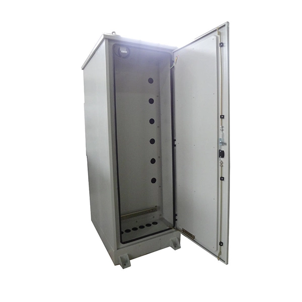
Nordic Fiberglass manufactures box pads for pad mount transformers, switchgear, and other pad mount equipment, sectionalizing cabinets, secondary pedestals, ground sleeves, hand holes and hill holders. Nordic Anti-Corrosion Supplies is a newly established company based in Sønderborg, Denmark, dedicated to providing high-quality equipment to the surface treatment industry. Get in touch with us! Copyright © 2026 Nordic Lights Ltd. All Rights Reserved. Search for a product. Born in Sweden 10 years ago, zebra® accompanies professionals in search of high-quality lighting solutions. The brand's reputation has been built around its strengths: design, technical expertise, reliability. Its. Zhejiang Guozhong Explosion-proof Electrical Co. is an all-inclusive manufacturer of explosion-proof electrical (electronic) equipment, covering design, research and development, production, inspection, sales and after-sales services. The company mainly produces over 150 series and 1,200.
[PDF]