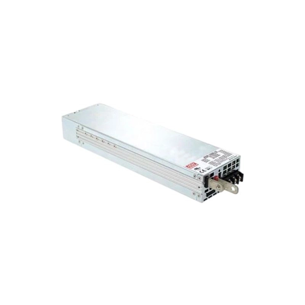
Welcome to our light sources category, where we offer advanced calibration solutions designed for precision and accuracy in scientific measurements. Our selection encompasses two primary subcategories: “Wavelength Calibration” and “Radiometric Calibration,” featuring state-of-the-art products. This. As a result of a 2-year research project, finalised in 2020, GL Optic developed new calibration facilities and created Calibration and Research Laboratory of Optical Radiation ( CARLO ). Today, CARLO is the only laboratory in Central and Eastern Europe equipped with the Black Body Radiator – the. We offer two types of light sources for calibration: Pen-Ray line sources for the wavelength calibration of spectroscopic instruments and calibrated irradiance sources covering UV-NIR. All Avantes spectrometers are factory wavelength calibrated and do not require recalibration as they have fixed slits and optics. Options include mercury-argon (253-1700 nm), krypton (427-893 nm), neon (540-754 nm), argon (696-1704 nm) and xenon (916-1984 nm) gas-discharge emission sources. Multiple LED sources can be efficiently combined into a single output beam, and offer major advantages such as long life-time, easily tunable spectrum, high power stability, and ultra-fast switching (on the microseconds level) without using moving mechanical components. Multi-Wavelength Collimated.
[PDF]
In fiber-optic communications, wavelength-division multiplexing (WDM) is a technology which multiplexes a number of optical carrier signals onto a single optical fiber by using different wavelengths (i.e., colors) of laser light. This technique enables bidirectional communications over a single strand of fiber (also called wavelength-division duplexing) as well as multiplication of capacity. The. SystemsA WDM system uses a at the to join the several signals together and a at the to split them apart. With the right type of fiber, it is possible to have a device that does both s. Originally, the term coarse wavelength-division multiplexing (CWDM) was fairly generic and described a number of different channel configurations. In general, the choice of channel spacings and frequency in these co.
[PDF]
Light decay in light divisions refers to the decrease in light intensity as it travels through optical fibers or other transmission media. This decay can occur due to a number of factors, including absorption, scattering, and reflection. If you don't know what kind of losses to expect in your system, you won't know how many other components. It is also known as fiber loss or signal loss. The signal attenuation of fiber determines the maximum distance between transmitter and receiver. Another important property of optical fiber is. Fiber loss, also called fiber optic attenuation or attenuation loss, refers to the loss of signal between input and output. Losses can be introduced by various means such as intrinsic material absorption, scattering, bending, connector loss and more. This loss can significantly reduce the effectiveness of optical fibers in applications such as telecommunications, imaging systems, and even simple fiber-optic tools like flashlights. In the early days of.
[PDF]
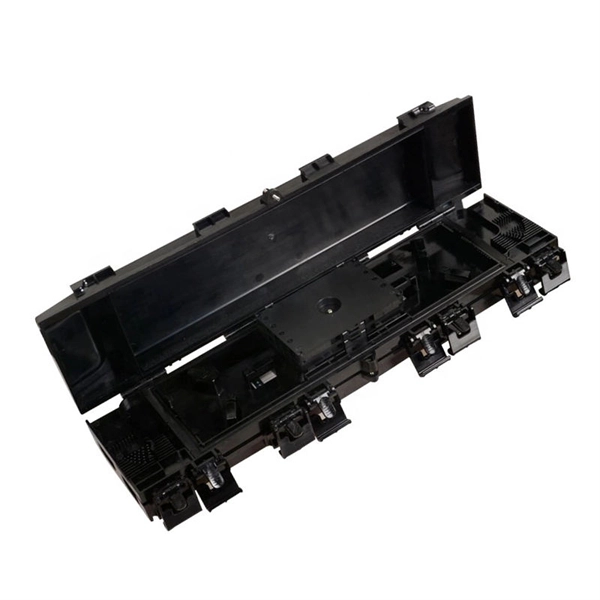
Through the adapter in the distribution box, the optical signal is led out by the optical jumper to realize the optical wiring function. An optical cable consists of three primary parts: the core, the cladding, and the protective sheath. The core is at the center of the optical cable and serves as the pathway for transmitting light signals. Surrounding the core is the cladding, which has a lower refractive index than the core. In the complex architecture of fiber optic networks, the Optical Distribution Frame (ODF) serves as the linchpin for organizing, protecting, and distributing optical signals. Whether in data centers, telecom central offices, or enterprise network rooms, ODFs enable efficient fiber management. The optical fiber distribution box is to protect the connection point where the optical cable is connected to the user end, so that the optical cable access point is stable, dustproof and waterproof. What is a fiber distribution box? 2. The. A fiber distribution box (FDB) functions as a central hub in fiber optic networks where the main cable is split into multiple individual fibers for distribution to end users. These boxes protect sensitive fiber connections from environmental factors while providing an organized framework for.
[PDF]

An optical attenuator is a passive device used to reduce the power level of an optical signal, either in free space or in an optical fiber. There are various types of them from the fixed ones, step-wise variable, and continuously variable. Signals may be attenuated. Fiber loss, also called fiber optic attenuation or attenuation loss, refers to the loss of signal between input and output. Losses can be introduced by various means such as intrinsic material absorption, scattering, bending, connector loss and more. It provides an expert-curated supplier directory, buyer-focused technical background information, and structured selection criteria to support professional procurement decisions. What is a Fiber-optic Attenuator?. To determine the power budget and power margin needed for fiber-optic connections, you need to understand how signal loss, attenuation, and dispersion affect transmission. Understanding the causes of signal loss and implementing mitigation strategies is essential for maintaining network efficiency. From infrastructure planners to telecom engineers. However, there is light leakage when PMMA optical fibers transmit concentrated sunlight, resulting in a transmission efficiency lower than the theoretical value. This research aims to quantitatively study the light leakage effect of PMMA optical fibers. Concentrated sunlight was used as the.
[PDF]
If the LOS light on your fiber router or ONT is blinking red, it usually means Loss Of Signal. This guide explains the likely causes, the checks you can do at home, and when the issue needs technician support. The LOS light on your router indicates the status of your internet connection to the Internet Service Provider (ISP). When it's green and steady, everything is fine. However, when it blinks red or stays solid red, it signifies a Loss of Signal, a problem preventing your router from communicating. That blinking red LOS light means your router has lost its connection to your internet provider's network. Before you panic or call tech support, there are several simple fixes you can try at home that often solve this problem in minutes. In most cases, a loss of signal indicates a technical issue with the. The tables in this article provide detailed information about the possible appearances of the LED lights on each device, the possible causes of each state, and what you should do. Ensure your Fiber Jack is connected to the network and the LED lights are connected and working properly before moving. Red light means LOS (Loss of Signal) on your fiber connection. Need to reach out to your ISP and have them diagnose signal loss Did you try turning it off and on again? Good old INACT ONT alarm. Thanks! LOS aka loss of signal indicates a line side issue occurring where the.
[PDF]
Resolving these issues involves steps like checking cable connections, soft resets, updating firmware, and specific solutions for different router brands like ASUS and Spectrum. It often indicates that something is wrong with your internet connection or the device itself. Fortunately, diagnosing and resolving these issues doesn't have to be complicated. In this comprehensive guide, we will walk you through the common causes of a red light on your router and provide. A router showing a red light can mean different things, like a service outage, misconfiguration, or loose connection, all of which can lead to a broken internet connection. Fortunately, there are heaps of ways to fix a red blinking light on your router. One of the first things you should try is to. Turn off the router and disconnect the power cord. Check that the PON cable is free from damage or sprains. Even if you have the best router, you may experience a loss of connection or other issues and see that dreaded red light. When it's green and steady, everything is fine. However, when it blinks red or stays solid red, it signifies a Loss of Signal, a problem preventing your router from communicating.
[PDF]
This comprehensive guide will equip you with the knowledge and steps needed to safely test a lighting circuit using a multimeter. We will cover the essential safety precautions, different testing methods, interpreting the results, and troubleshooting common issues. Understanding the principles. Multimeters are versatile tools used by electricians and hobbyists alike to diagnose electrical problems and ensure the proper function of electrical devices. We'll explain how to measure AC and DC voltage, test for continuity, measure capacitance, measure frequency, and test diodes. Hence the 'multi'-'meter' (multiple measurement) name. The most basic things we measure are voltage. Here is a step-by-step guide on how to test a light fixture with a multimeter for beginners: Step 1: Turn Off the Power Before you begin testing the light fixture, it is crucial to turn off the power to the fixture at the circuit breaker. It's an indispensable tool for troubleshooting and maintaining electrical circuits. Different types of multimeters offer varying degrees of precision and. An easy way to test a light fixture is to remove the bulb and replace it with one that you know is working. If you don't happen to have a working bulb handy, you can use a light socket tester or test the fixture with a multimeter.
[PDF]