An Optical Splitter, also known as a beam splitter, is a passive optical device that divides a single input optical signal into two or more output signals. Conversely, it can also combine multiple signals into one. Beamsplitters are often classified according to their construction: cube or plate. Schematic illustration of a beam splitter cube. In practice, the reflective layer absorbs some light. It is a crucial part of many optical experimental and measurement systems. Modern microscopes have a variety of objectives, mirrors, and pinholes in order to obtain the best image (Figure 1B). The component of interest here is the beam splitter. Figure 1: The light path through different microscopes. A) An early compound microscope with a basic light path. The light goes. 📦 For purchasing, use the RP Photonics Buyer's Guide for beam splitters. It provides an expert-curated supplier directory, buyer-focused technical background information, and structured selection criteria to support professional procurement decisions. They help divide and manage light beams for various applications. Without them, many optical setups would not function properly. The split ratio of light transmittance and reflectance is 1:1 and is called a half mirror. Good fit for large beam size applications at a reasonable price. Advantages are: minimal.
[PDF]
In its most common form, a cube, a beam splitter is made from two triangular glass prisms which are glued together at their base using polyester, epoxy, or urethane-based adhesives. (Before these synthetic resins, natural ones were used, e. ). A beam splitter or beamsplitter is an optical device that splits a beam of light into a transmitted and a reflected beam. It is a crucial part of many optical experimental and measurement systems, such as interferometers, also finding widespread application in fibre optic telecommunications. Beamsplitters are often classified according to their construction: cube or plate. The world's top manufacturers Edmund Optics and Schott dominate the high-end market, and Chinese manufacturers are accelerating their rise. New materials and intelligent production are driving higher precision breakthroughs, enabling innovations in spectral analysis, laser technology and. At its essence, a beam splitter is a device that can direct light into two unique paths. Most beam splitters are fabricated from glass cubes. When a light beam comes into contact with these cubes, half of it enters the glass, while the other half is reflected. These tools can split both laser and regular light. This division allows for the simultaneous analysis or utilization of the light's properties along two separate paths. The device is purely.
[PDF]
Beam splitters are essential optical devices used in various applications to divide a light beam into two or more distinct paths. These devices are fundamental in the field of optics, playing a crucial role in interferometry, laser systems, and even photography. It is a crucial part of many optical experimental and measurement systems, such as interferometers, also finding widespread application in fibre optic telecommunications. In its. About light behaviour on a beamsplitter A half mirror is designed with reflectance and transmission of light with a 1:1 ratio. If light incident direction and polarization conditions change, it may impact the ratio. Reflection properties change when light is projected onto the. 📦 For purchasing, use the RP Photonics Buyer's Guide for beam splitters. It provides an expert-curated supplier directory, buyer-focused technical background information, and structured selection criteria to support professional procurement decisions. They play a crucial role in various scientific, industrial, and everyday applications. To fully understand how beam splitters work, it is important to delve into their operational. Explore the precision, applications, and design principles of beam splitters, essential for advancements in scientific research and technology.
[PDF]
Plate beamsplitters do not require optical cement to hold the two halves of the prism together. This is an advantageous feature because lasers can rapidly damage cement, and it is prone to breaking down with ongoing exposure to UV light. Beamsplitters are fundamental components in optical engineering, serving to precisely divide a single input beam of light into two distinct output beams. This division allows for the simultaneous analysis or utilization of the light's properties along two separate paths. It is a crucial part of many optical experimental and measurement systems, such as interferometers, also finding widespread application in fibre optic telecommunications. In its. A beam splitter (or beamsplitter, power splitter) is an optical device which can split an incident light beam (e. a laser beam) into two (or sometimes more) beams, which may or may not have the same optical power (radiant flux). These versatile tools can split both laser and regular light, depending on the application in question. Additionally, beamsplitters can be used in reverse to combine two different beams into a single one.
[PDF]
The input beam is spatially separated into two orthogonally polarized beams, diverging at an angle determined by the prism geometry and the material's properties. Beamsplitters are fundamental components in optical engineering, serving to precisely divide a single input beam of light into two distinct output beams. This division allows for the simultaneous analysis or utilization of the light's properties along two separate paths. It is a crucial part of many optical experimental and measurement systems, such as interferometers, also finding widespread application in fibre optic telecommunications. Additionally, beamsplitters can be used in reverse to combine two different beams into a single one. Polarizing beam splitters selectively transmit or reflect light depending on their polarization state, making them essential in a variety of optical applications.
[PDF]
Non-polarizing beamsplitters are specified by their splitting ratio, i. the ratio of P-polarized light to. A beam splitter or beamsplitter is an optical device that splits a beam of light into a transmitted and a reflected beam. It is a crucial part of many optical experimental and measurement systems, such as interferometers, also finding widespread application in fibre optic telecommunications. a laser beam) into two (or sometimes more) beams, which may or may not have the same optical power (radiant flux). Newport offers a wide variety of Beamsplitters in various shapes. Circular beamsplitters, plate beamsplitters and cube beamsplitters can be purchased for polarizing or non polarizing beamsplitting. DST beam splitters divide incident light into transmission and reflection components at defined ratios. The dielectric coating on the front surface determines the splitting ratio, partially reflecting and transmitting light beams, lasers, or images. These versatile tools can split both laser and regular light, depending on the application in question.
[PDF]
The beam splitter splits and then recombines infrared radiation, while the detector picks up the resulting signal. It's sensitive to both intensity and frequency. Together, they decide just how accurately an instrument captures those unique infrared “fingerprints” from different. Beam splitters are integral optical components that divide a beam of light into two or more separate beams. Their precision and versatility make them indispensable in a variety of scientific, industrial, and technological applications. It is a crucial part of many optical experimental and measurement systems, such as interferometers, also finding widespread application in fibre optic telecommunications. This precise ability to split light by wavelength makes beam splitters essential in various fields, including laser systems, semiconductor. 📦 For purchasing, use the RP Photonics Buyer's Guide for beam splitters. It provides an expert-curated supplier directory, buyer-focused technical background information, and structured selection criteria to support professional procurement decisions. What are Beam Splitters? A beam splitter (or. When splitting one incident light beam into two separate beams, beamsplitters are applied. Depending on the beam split based on intensity, wavelength, or polarization, its level of optical power on beam penetration differ. Just to mention few, these beamsplitter components are commonly required for.
[PDF]
Beamsplitters are fundamental components in optical engineering, serving to precisely divide a single input beam of light into two distinct output beams. This division allows for the simultaneous analysis or utilization of the light's properties along two separate paths. It is a crucial part of many optical experimental and measurement systems, such as interferometers, also finding widespread application in fibre optic telecommunications. Their precision and versatility make them indispensable in a variety of scientific, industrial, and technological applications. This article explores the principles behind beam splitters. Beamsplitters can be used in a wide range of fields, such as optics and interferometry. These important devices come in different forms and have many different applications, but many people are unsure of the key principles of their use. The library includes research papers, conference proceedings, technical articles, and book chapters that cover both theoretical and.
[PDF]
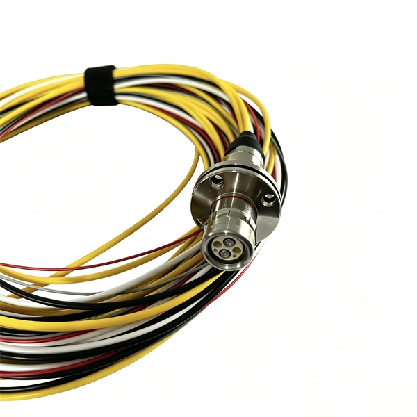
The hydraulic wrench head and power pack are connected by a 10,000 psi (68,900 kPa) single-line hose assembly. Each end of the hose will have one female connector. When you install a distribution box, you need a variety of tools to get the job done safely and efficiently. A measuring tape and. Never connect or disconnect any hydraulic hoses or fittings without first unloading the wrench and the pump. Open all hydraulic controls several times to make sure the system has been completely depressurized. If the system includes a gauge, double check the gauge to make sure pressure has been. et that came with your hydraulic t lly inspect all components for shipping damage. If ximum Working Pressure is 10,000 PSI (700 bar). We use baier high pressure hoses to connect the torque wrench and hydraulic pump. Some illustrations in this manual may show details or attachments different from your hoist. Some components have been removed for illustrative purposes. Drawings. Overview The Enerpac S-Series hydraulic torque wrench is designed for controlled tightening and loosening of fasteners in industrial bolting applications. The wrench features a removable square drive shaft that is designed to accept a wide variety of interchangeable hex sockets of different sizes.
[PDF]
In this step-by-step tutorial, we'll cover: ✅ Tools you need ✅ Safety precautions ✅ Mounting the box ✅ Wiring tips ✅ Final checks Perfect for beginners, DIYers, and electricians who want a clear installation guide. more Learn how to properly install an electrical box . Learn how to install a distribution box safely and correctly. Covers wiring, placement, standards, and expert tips for a compliant setup. A distribution box is the heart of any electrical system. It takes the incoming power and safely distributes it to different circuits throughout your building. Whether you are an electrical contractor or a construction brigade, knowing how to properly and safely install distribution boxes is the basis of ensuring the safe operation of the entire system. Material preparation: Prepare the required circuit breakers, wires, wiring ties and other materials, and ensure that they meet the design drawings and installation requirements. It serves as a central hub for distributing electricity throughout a building, ensuring that power is delivered safely and efficiently to all the required locations.
[PDF]
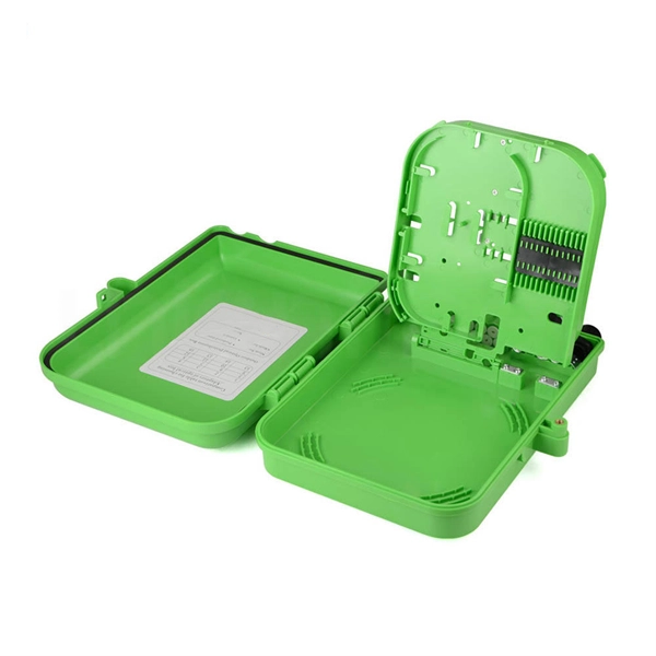
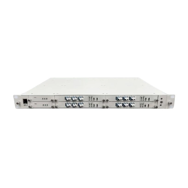
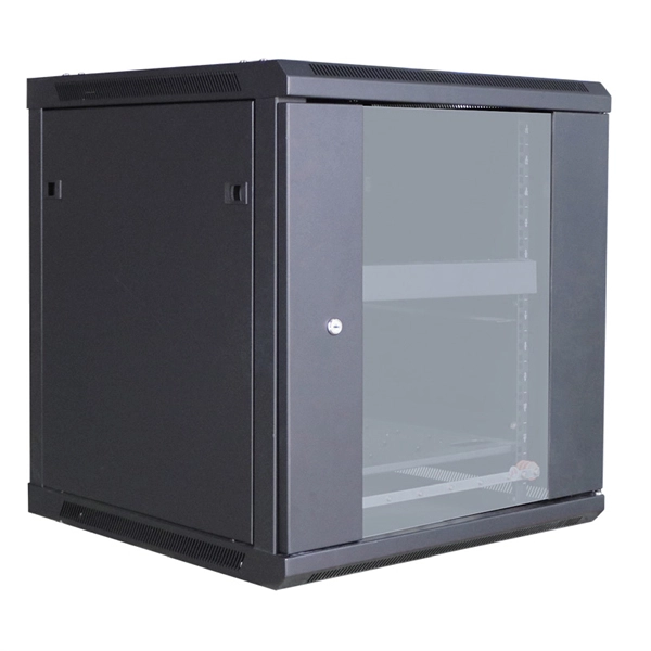
Learn how to install a fiber distribution cabinet step by step, including mounting, cable routing, grounding, and testing for FTTH networks. The installation of a fiber distribution cabinet involves five key steps: site selection, cabinet mounting, cable routing, fiber splicing, and grounding +. This step is very simple, we only need to install brackets on both sides of the optical fiber distribution box, and then fix the brackets to the designated position of the rack with screws. It should be noted that before installing the optical fiber distribution box, the installation direction of. Keeping this page as a placeholder for now. Have any questions? Talk with us directly using LiveChat. Read and understand this procedure (as well as the instructions provided with related assemblies) before beginning an installation. Do not discard this instruction; keep it on hand for future reference. Familiarize yourself to understand the unit's placement in your network. The 1U fiber optic distribution box is used as an example to introduce its structure. Three adapter panels can be installed on the front panel of this fiber optic distribution. Fiber Distribution Hub Installation Procedure - Optical Cable Corporation Products Fiber Copper Hybrid Cabinets, Racks, Enclosures Deployable Solutions Industries Oil & Gas Mining Industrial BroadcastAV Military Commercial Enterprise library & Support Contact Resources About OCC News Careers.
[PDF]
A neat, well-organized subpanel bundles wires to conserve space and improve access. Ideally, wire groups are installed in layers and wires are bent at right angles to buses or breakers. Label short sheathing sections (slugs) to indicate which circuits wires serve. Choose the right box based on environment (indoor/outdoor), load capacity, and durability. Check for proper IP/NEMA ratings and material quality. Ensure safe placement: install in dry, accessible areas with good ventilation and at appropriate height (typically ~1. Practice good wiring: secure. Box installation: Make sure that Distribution box has been correctly installed and fixed. Material preparation: Prepare the required circuit breakers, wires, wiring ties and other materials, and ensure that they meet the design drawings and installation requirements. And all the switching and protective devices are installed in the. Wiring distribution panels serve as the central hub and nerve center, routing power from the main service feed to multiple circuits. When setting up such a significant component of industrial, commercial, and utility applications, it's essential to get everything right. Labeling cables at outlets is.
[PDF]
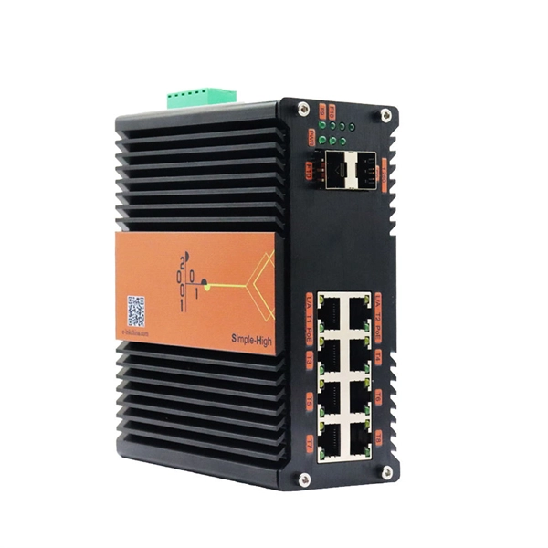
Insert a compatible SFP transceiver into the converter's port, making sure it matches the network's media type and speed. Then, connect one end of the fiber cable to the transceiver and the other to the appropriate port on a switch, router, or another media converter. Fiber media converters translate copper's electrical signals into fiber's optical signals, and back again. This allows networks to extend beyond the 100 m copper limit while gaining higher bandwidth and resistance to electromagnetic interference. In the illustrated setup, each LAN links to a. A fiber media converter is a networking device that allows you to convert a signal from one medium to another. This allows you to connect devices that use different types of cabling, such as a computer. While fiber optic ports are becoming increasingly common on networked electronics, the majority of connected devices still rely on RJ45 twisted pair connections. To help bridge the copper-fiber divide, media converters and transceiver modules (also known as SFPs or mini-GBICs) are often required. Use Fiber Media Converter in Your Network Media converters today are widely deployed in all. It is a device used to convert fiber optic cables to Ethernet cables to provide better connectivity. It is necessary to convert fiber optic signals to Ethernet signals because many network devices can only communicate with Ethernet signals. Fiber optic cables are known for the unmatched speed.
[PDF]
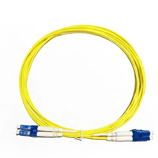
Use this worksheet to input values for all variables that will impact your system's performance. After entering your values, please ensure you click the 'Calculate Link Loss' button at the bottom of the page to generate your total link loss. Add connectors, splices, bends, and safety margin easily. See results instantly above the form, then adjust values. Choose a mode, then enter values and optional losses. All calculations use base-10 logarithms. mW must be greater than zero. Used only in measured attenuation mode. Length is needed. The power budget refers to the amount of fiber optic cable plant loss that a datalink (transmitter to receiver) can tolerate in order to operate properly. Sometimes the power budget has both a minimum and maximum value, which means it needs at least a minimum value of loss so that it does not. To detect whether the link runs properly, the following calculation should be performed. It is often the case to calculate the maximum signal loss across a given fiber link during optical cable installation. First, you should be aware of the fiber loss formula: The Total Link Loss = Cable. Therefore, it is very important to calculate the fiber loss and take appropriate steps. In order to get the most reliable results, an Optical Time Domain Reflectometer (OTDR) trace of the actual fiber connection should be completed. This will provide you with the real.
[PDF]
The fastest way to test a fluorescent tube is with a multimeter set to continuity mode. Each end of the tube has two pins connected by a thin filament inside the glass. If either filament is broken, the tube is dead. The whole test takes about 30 seconds per tube once you know what. Knowing how to use a multimeter to check an LED tube light is a valuable skill for homeowners, electricians, and anyone involved in maintaining lighting systems. Perhaps it's a simple wiring problem, a. One essential tool for diagnosing LED tube light issues is a multimeter. This process measures electrical resistance to determine if the tube has suffered an internal failure before replacing the bulb or investigating the ballast. If you don't have a multimeter to use, a simple coin cell battery holder with leads will let you know. Yes, you absolutely can test an LED light with a multimeter! It's a straightforward process that helps you figure out if your LED is working or if it's the source of a problem in your circuit.
[PDF]